 Complaint

| safety symbols | signification |
| Danger | Indicates that if the safety warning is ignored, there is a serious accident that may lead to personal injury. |
| Warning | Indicates that if safety warnings are ignored, there is a risk of serious injury, serious equipment damage or major business interruption. |
| Notice | This means that if safety warnings are ignored, there is a risk of moderate injury, moderate equipment damage or partial business interruption. |
Insturction | Indicates that the content is additional information for the body. |
| Warning! All installation operations on the controller must be performed by a qualified technician. Professional and technical personnel must undergo special training, complete the manual and understand the safety related to the operation. If a non-professional person performs installation operations and causes personal injury, the company will not be responsible. Failure to install and operate the controller in accordance with the instructions in this manual will result in damage to the controller and will not be covered by our warranty. |
| Notice! When receiving the product, first check the MPPT series controller for damage during transportation. If you find any problem, please contact our company or the transportation company immediately. |
| Warning! Damage to the MPPT controller caused by the following conditions, or other damages will not be covered by our warranty. When configuring the PV array, ensure that the maximum short-circuit current on the DC side is within the allowable range of the MPPT controller, otherwise the MPPT may be irreparable. When configuring the PV array, make sure that the open circuit voltage of each PV string does not exceed the maximum input range of the MPPT controller, otherwise the MPPT controller will be irreparable. The selected controller charging current should not be greater than 0.3 times the battery capacity. If it is greater than the battery will be damaged or the battery life will be reduced. Improper selection of the MPPT controller installation environment will affect machine performance and may cause machine damage. Do not install the MPPT controller in a flammable or explosive place or in a place where flammable or explosive materials are stored. Do not install the MPPT controller in an explosive location. Do not install the MPPT controller in a location where it may be exposed to lightning strikes. Do not install the MPPT controller in a place with a lot of salt spray. Good ventilation is required when the MPPT controller is in operation. The MPPT controller needs to be installed upright and ensure that the air duct is unobstructed. |
| Warning! Always disconnect the PV array, battery, load, etc. (circuit breaker) or fuse before all devices are fully connected. Prevent water from entering the inside of the controller. |
| Note! All electrical installations must comply with local and national electrical installation standards. To ensure safe operation, proper grounding, proper conductor size and the necessary short-circuit protection are required. The connection cable must be selected to the appropriate specifications, and the connection is secure and well insulated. After installation, check that all wiring connections are tight to avoid the risk of heat build-up due to virtual connections. |
| Danger! Do not open the machine cover while the MPPT is powered! |
| Danger! Repair work must be carried out by professional service technicians. The machine needs to be powered off before maintenance, and it can be disassembled after waiting for 5 minutes after power off. |
| parameter name | Weight and Size | |||
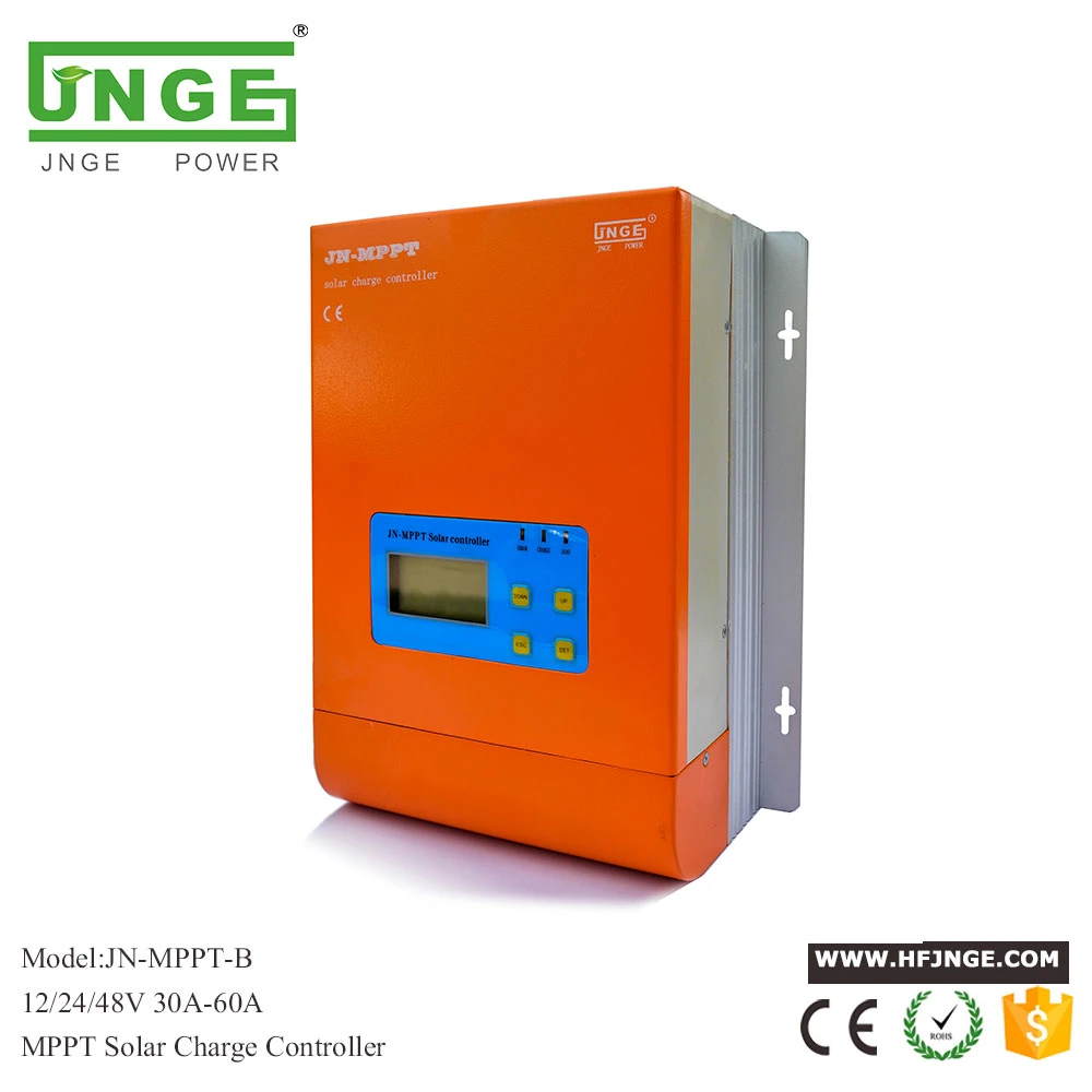
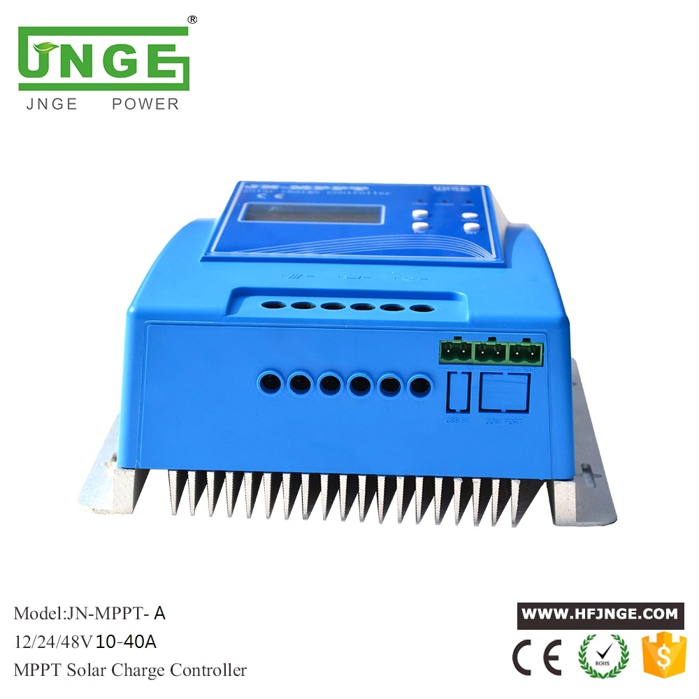
| Model no. | JN-MPPT-MINI | JN-MPPT-AL | JN-MPPT-BL | JN-MPPT-CL |
| weight(kg) | 1.25Kg | 1.5kg | 2.3kg | 3.6kg |
| Size L*D*H(mm) | 156*134*81mm | 186*146*81mm | 240*170*97mm | 340*208*95mm |
| Danger! Explosion hazard! Never install the controller and battery in the same confined space! Also do not install in a confined space where battery gas may collect. |
| Note: For installation safety, we recommend a wiring sequence Note: The MPPT series controller is a common negative design. |
| Caution: Do not connect the electrical equipment that exceeds the surge power of the controller to the load terminal to prevent damage to the controller! |
| Warning: When you need to use the mobile, make sure that all the wirings are fixed. Because the virtual connection points may cause heat to accumulate, it may cause fire in severe cases; |
| Warning: Do not connect the PV panel to the battery terminal of the controller, as it will burn out the controller.It is strictly forbidden to make the battery positive or negative, extremely short circuit, otherwise it will cause fire or explosion hazard, please be careful. |
| Caution!
|
| Photovoltaic electrical parameters | ||||
| MODEL | JN-MPPT-MINI | JN-MPPT-AL | JN-MPPT-BL | JN-MPPT-CL |
| PV array open circuit voltage range | 20V~100V (12VA battery system) | |||
| 40V~145V (24V battery system) | ||||
| 80V~145V (48V battery system) | ||||
| 120V~250V (96V battery system) | ||||
| Cable selection table | ||||||||||
| Current level /A | 10 | 20 | 30 | 40 | 50 | 60 | 70 | 80 | 100 | 120 |
| Wire diameter /mm2 | 2 | 4 | 6 | 8 | 10 | 12 | 14 | 16 | 20 | 24 |
| AWG | 14 | 11 | 9 | 8 | 7 | 6 | 5 | 5 | 4 | 3 |
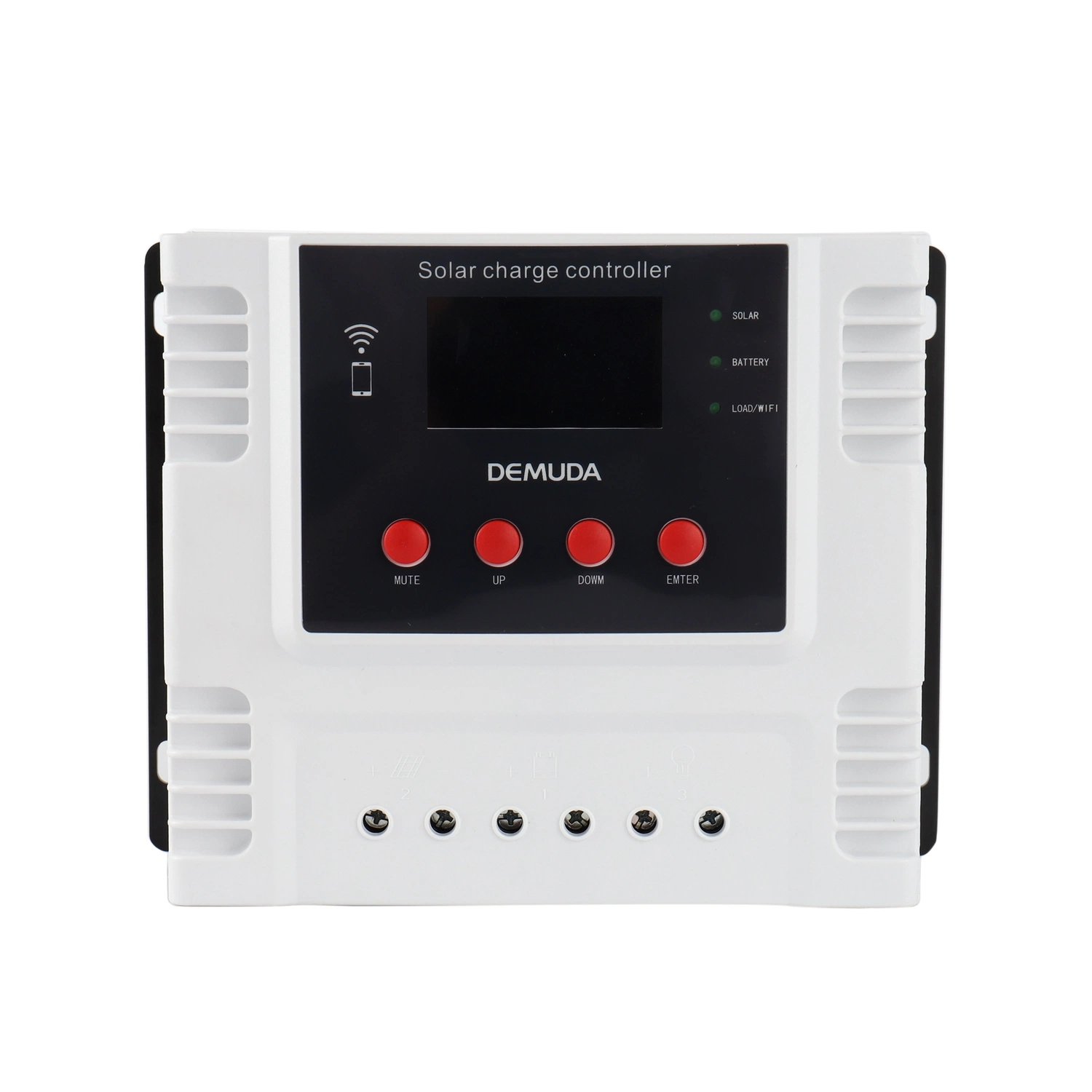
| Indicator light | status | definition | Remarks | |
| 1 | Fault indicator (red) | Extinguished | Working normally, no fault | |
| 2 | Constantly light on | error | ||
| 3 | Charging indicator (yellow) | Light off | No charging | |
| 4 | Light on | MPPT charging | ||
| 5 | Slow flashing | Floating charge | ||
| 6 | Fast flashing | Boost charging | ||
| 7 | Output indicator (green) | Light on | Output normally | |
| 8 | Light off | Light control, timing light normally off output | ||
| 9 | Slow flashing | Battery over discharge off load | ||
| 10 | fast flashing | Battery over discharge off load |
| button | Effect | Remarks |
| SET | Function 1: Main menu key, function 2: parameter setting save key; | |
| ESC | Exit the setup interface button; | |
| UP | Function 1: display page on page display, function 2: parameter setting plus; | |
| DOWN | Function 1: Display page under parameter, function 2: parameter setting minus; |
| Icon name | definition | Function Description |
| day | The icon lights up to indicate daylight | |
| night | The icon lights up to indicate the night | |
| Solar panel | The icon lights up to check the PV array access | |
| battery | The icon lights up to indicate battery access and the inside indicates battery voltage | |
| load | The load is lit to indicate that the load has an output | |
| Status icon | The icon lights up and scrolls to indicate the chargevstatus and discharge status,respectively. | |
| Failure icon | The icon flashes to indicate that the system has a fault condition. |
| Field Name | definition | Function Description |
| Vbattery | Battery voltage | The field lights up and the current battery voltage is displayed in the data display area. |
| VPV | Solar panel voltage | The field lights up and the current PV panel voltage is displayed in the data display area. |
| Icharge | Charge current | The field lights up and the current battery charging current is displayed in the data display area. |
| Iload | Discharge current | The field lights up and the current battery discharge current is displayed in the data display area. |
| Under | Over discharge voltage | The field lights up to set the battery over-discharge voltage. When the battery is under voltage, this field flashes. |
| Under-R | Over discharge return | The field is lit and the battery over-discharge return voltage can be set. |
| OVD | Over charge volatge | The field lights up to set the battery overcharge voltage. This field flashes when the battery is overcharged. |
| OVD-R | Over charge return | The field is lit and the battery overcharge return voltage can be set. |
| Float | Float charge voltage | The field lights up to set the battery float voltage, and the field flashes during the float phase. |
| BCV | Boost charge | The field lights up to set the battery to raise the charging voltage, and the field flashes during the boost charging phase. |
| Time | Time control period 1 setting | The field lights up, and the first time period can be set (the light control lights up for the first time). When the 24 is set, the controller is the household mode. The default is 24 hours. |
| Time1 | Time control period 2 setting | The field lights up. In the street light mode, the second time period can be set (the light control time is after the light control is turned on). |
| Time2 | Time control period 3 setting | The field lights up. In the street light mode, the third time period can be set (the light control is illuminated for the second time). |
| L-CON-V | Light control voltage setting | The field is lit, the first digit of the display area is displayed 1, and the light control can be set to turn on (light control lighting) voltage; after the light control is turned on, the first digit is displayed 2, and the light control can be set to turn off (lighting off) |
| MPPT | MPPT charging | This field flashes during the MPPT charging phase. |
| ERROR | ERROR | This field lights up when there is a fault |
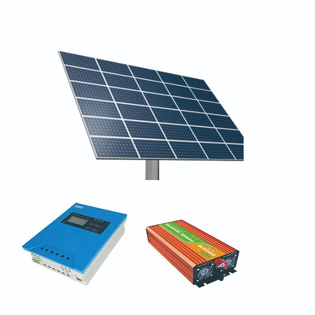
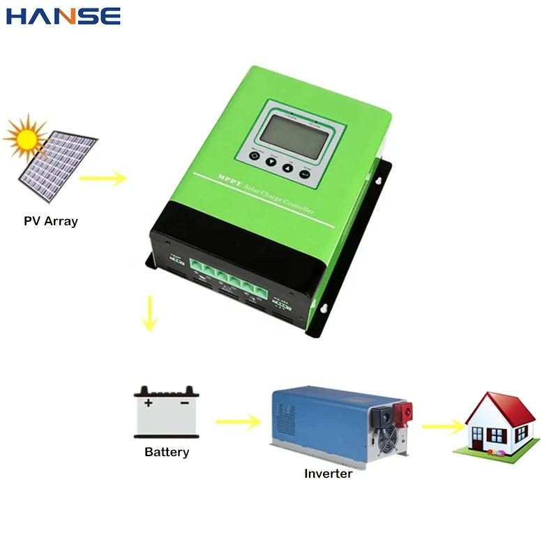
Instruction | The PC host computer or APP (WIFI or GPRS mode) is an optional accessory. The device can only use one mode for single communication, and cannot use several communication modes at the same time! |
| Protection function | instruction |
| PV over voltage protection | When the PV array charging voltage exceeds the controller's rated input voltage range, charging will stop. |
| Battery polarity reverse connection | When the polarity of the battery is reversed, the controller will not work and will not be damaged. After correcting the wiring error, re-open the opportunity to continue normal operation. |
| Battery over discharge protection | When the battery voltage is lower than the set undervoltage value, the discharge of the battery will be automatically stopped to prevent the battery from being over-discharged and damaged. |
| Battery overload protection | When the controller output current is greater than the set value, the load output will be automatically stopped to prevent the battery from being over-discharged and damaged. |
| Battery over volatge protection | When the battery voltage reaches the overvoltage protection setting value, the battery will be automatically stopped to prevent the battery from being overcharged and damaged. |
| Night anti-reverse protection | At night, since the battery voltage is greater than the voltage of the photovoltaic module, the automatic protection prevents the battery voltage from being discharged through the photovoltaic module; |
| Equipment overheat protection | The controller has its own temperature sensor. When the temperature is higher than the set value, the charging will stop. When the temperature is lowered, it will automatically start to work. |
| High voltage surge | This controller can only protect high-voltage surges with low energy. In areas with frequent lightning, it is recommended to install an external lightning arrester. |
| ERROR | Indicator status and alarm icon | possible reason | Solution |
| Array over voltage | Red light, icon flashes | More PV arrays in series | Disconnect the PV array, reduce the number of PV arrays connected in series, and ensure that the PV array open circuit voltage does not exceed the set value in the "Table 3-1 PV Electrical Parameters" table; |
| Battery over voltage (overcharge) | Red light on,OVDandflashes | 1. The controller overvoltage protection point is lower than the highest charging range; 2. The battery is aging or over-discharged; 3. The battery is over-discharged; 4. Large dynamic changes in load; | 1. Reset the battery overvoltage protection point through the device button or PC host computer or APP; 2. The battery needs to be replaced after aging; 3. Over-discharge requires manual setting of battery voltage level; 4. Reduce large dynamic changes in load; |
| Battery under voltage (over discharge) | Under and flashes | Battery voltage value is lower than the undervoltage protection setting | 1. Reduce or disconnect the load. If the alarm is released, the battery voltage returns to normal, indicating that the load power is too large or the battery voltage and capacity are low. It is easy to cause undervoltage protection with heavy load; 2. Disconnect the load controller and still alarm, the battery voltage does not return to the over-discharge recovery setting value, and the battery pack needs to be charged by PV or other means, so that the fault can be released after the battery pack voltage reaches the recovery point set value. |
| The indicator light is off and the display is not displayed. | Battery voltage is lower than device startup voltage | ||
| Heat sink overheating | Red light on, flashes | 1. The ambient temperature is too high, the heat dissipation of the equipment is poor, and the fan is not well ventilated; 2. The fan is damaged. | 1. Check the installation environment of the equipment, remove the debris of the equipment, and ensure that the fan is ventilated smoothly; 2. The fan needs to be replaced if it is damaged. |
| Charge current | Red light on,Icharge flashes | Charging overcurrent protection check for abnormal current detection and malfunction | If you restart it several times, if you can't solve it, you need to go back to the factory for repair; |
| Over loading | Red light on, flashes | Load power is too large | 1. Reduce the load power; 2. Restart and release the fault; 3. Without excessive sensibility and capacitive load; |
| Remark: The above fault phenomenon can not be turned on except the battery under voltage, other faults can refer to the fault information through the PC background or mobile APP; | |||
Note: Danger of electric shock! When doing this, you must ensure that all power to the controller has been disconnected before performing the appropriate checks or operations! |
| parameter name | Parameter value (and adjustable range) | |||||||||||||||
| MODEL | JN-MPPT-MINI | JN-MPPT-AL | JN-MPPT-BL | JN-MPPT-CL | ||||||||||||
| Current rating (A) | 10 | 20 | 30 | 30 | 40 | 50 | 30 | 40 | 50 | 60 | 70 | 50 | 60 | 80 | 100 | 120 |
| Maximum charging current (A) | 10 | 20 | 30 | 30 | 40 | 50 | 30 | 40 | 50 | 60 | 70 | 50 | 60 | 80 | 100 | 120 |
| PV maximum input power (12V) (W) | 150 | 250 | 400 | 400 | 500 | 600 | 400 | 500 | 600 | 750 | 850 | 600 | 750 | 1000 | 1200 | 1450 |
| PV maximum input power (24V) (W) | 300 | 500 | 800 | 800 | 1000 | 1200 | 800 | 1000 | 1200 | 1500 | 1700 | 1200 | 1500 | 2000 | 2400 | 2900 |
| PV maximum input power (48V) (W) | 600 | 1000 | 1600 | 1600 | 2000 | 2400 | 1600 | 2000 | 2400 | 3000 | 3400 | 2400 | 3000 | 4000 | 4800 | 5500 |
| PV maximum input power (96V) (W) | -- | -- | -- | -- | -- | -- | -- | -- | -- | -- | -- | -- | -- | -- | -- | -- |
| Output maximum current A | 10 | 15 | 15 | 15 | 20 | 25 | 15 | 20 | 25 | 30 | 35 | -- | -- | -- | -- | -- |
| System identification voltage range v | 12V battery sysem | DC9V-DC16V | ||||||||||||||
| 24V battery system | DC18V-DC32V | |||||||||||||||
| 48V battery system | DC42V-DC60V | |||||||||||||||
| 96V battery system | 96V is a stand-alone system | |||||||||||||||
| PV panel open circuit input voltage range v | 20V~100V(12V battery system) | |||||||||||||||
| 40V~145V(24V battery system) | ||||||||||||||||
| 80V~145V(48V battery system) | ||||||||||||||||
| 120V~250V (96V battery system) | ||||||||||||||||
| MPPT efficiency | >99.5% | |||||||||||||||
| Conversion efficiency | >98% | |||||||||||||||
| Operating mode | The default is the household mode 24H | |||||||||||||||
| Lead-acid batteries | |||||
| System rated voltagev | 12V system(1 in series) | 24Vsystem(2in series) | 48Vsystem(4in series) | 96V system(8series) | 12Vdefault |
| Over voltage (overcharge)(v) | 13~17V | 26~34V | 52~68V | 104~136V | 15.5V |
| Over voltage return (v) | 13~17V | 26~34V | 52~68V | 104~136V | 15V |
| Charge limit voltage(v) | 9~15V | 18~30V | 36~60V | 72~120V | 14.9V |
| Boost charge(v) | 9~15V | 18~30V | 36~60V | 72~120V | 14.4V |
| Boost charge return(v) | 9~15V | 18~30V | 36~60V | 72~120V | 13.9V |
| Float voltage (v) | 9~15V | 18~30V | 36~60V | 72~120V | 13.8V |
| Over discharge (v) | 7~13V | 14~26V | 28~52V | 56~104V | 10.8V |
| Over discharge return(v) | 9~15V | 18~30V | 36~60V | 72~120V | 13.1V |
| Ternary lithium battery (single section 3.7V) | |||||
| System rated voltagev | 12Vsystem(default 3 in series) | 24V system(default 6 in series) | 48Vsystem(default 12 in series) | 96Vsystem (d efault24seires) | 3in series default value |
| Over voltage (v) | 10.5~15V | 21~30V | 42~60V | 84~120V | 13.5V |
| Over voltage return (v) | 10.5~15V | 21~30V | 42~60V | 84~120V | 12.6V |
| Charge limit voltage(v) | 10.5~15V | 21~30V | 42~60V | 84~120V | 12.6V |
| Boost charge(v) | 10.5~15V | 21~30V | 42~60V | 84~120V | 12.3V |
| Boost charge return(v) | 10.5~15V | 21~30V | 42~60V | 84~120V | 12V |
| Float voltage (v) | 10.5~15V | 21~30V | 42~60V | 84~120V | 12.3V |
| Over discharge (v) | 6~12V | 12~24V | 24~48V | 48~96V | 9.3V |
| Over discharge return (v) | 6~13.5V | 12~27V | 24~54V | 48~108V | 10.5V |
| Lithium LIFEPO4(single section 3.2V) | |||||
| System rated voltage | 12Vsystem(default 3 in series) | 24V system(default 6 in series) | 48Vsystem(default 12 in series) | 96Vsystemdefault24seires) | 3in series default value |
| Over voltage (v) | 9~12V | 18~24V | 36~48V | 72~96V | 11.7V |
| Over voltage return(v) | 9~12V | 18~24V | 36~48V | 72~96V | 11.1V |
| Charge limit voltage(v) | 9~12V | 18~24V | 36~48V | 72~96V | 11.1V |
| Boost charge limit (v) | 9~12V | 18~24V | 36~48V | 72~96V | 10.8V |
| Boost charge return(v) | 9~12V | 18~24V | 36~48V | 72~96V | 10.2V |
| Float voltage(v) | 9~12V | 18~24V | 36~48V | 72~96V | 10.8V |
| Over discharge (v) | 6~9V | 12~18V | 24~36V | 48~72V | 8.4V |
| Over discharge return(v) | 6~12V | 12~24V | 24~48V | 48~96V | 9.6V |
| Storage temperature(ºC) | -40ºC~80ºC | ||||
| Humidity(ºC) | 10% ~ 90% no condensation | ||||