Description
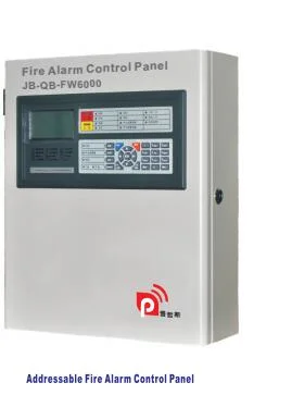
OverviewThe DT106 intelligent Fire Alarm Control panel offer unprecedented performance with special intelligent processing. In stand-alone or network configurations, D-TECTRON fire alarm system is ideally suited for new and retrofit commercial, institutional and industrial fire detection and notification applications. It supports 4 Addressable Loop Circuits and 1,008 addressable devices/points, 4 Notification Appliance Circuits, 5 form C dry relay contacts.
The DT106 provides one Class A or Class B intelligent device loop that supports up to 252 device addresses per SLC. Loop controller modules may be added in combination to expand total system capacity in 252-point increments to up to 1,008 device addresses. The DT106 panel includes four NACs that may be wired for either Class A or Class B operation. The panel connects with 4 remote annunciators, via CAN bus to form the fire alarm detection system.
FeatureDigital signal processor based design speeds installation time
Up to 252 device per SLC, max 4 loops with 1008 device addresses.
Form C contacts for alarm and trouble, Form C for supervisory
Easy-to-configure rotary addressing
Optional Ethernet port for programming
Supports horn silence over two wires, and UL 1971-compliant strobe synchronization
Class B or Class A wiring
Ground fault detection by module
Supports up to 4 LCD annunciators
Upload/Download locally
Alarm verification by point
7" colour LCD and a resolution of 800×480
Standalone operation or Networkable
Up to 64 Interconnected Fire Alarm Control Units
ApplicationD-TECTRON fire alarm systems can be configured with just a few devices for small size building applications, or networked with many devices to protect a large campus or a high-rise building. Simply add additional peripheral equipment to suit the application. Our advanced technology delivers supports the installers to do complete installation easily through simple steps.
ReliabilityThe inherent fault-tolerant characteristics of Analog/Address- able Technology boosts the reliability of D-TECTRON fire alarm systems. When combined with D-TECTRON smoke and heat detectors, these systems deliver a level of reliability and dependability for both small to medium size applications.
Perfect solution for retrofits and medium size facilityD-TECTRON Series control panels are designed for new, retrofit and medium facility applications. All connections are made over standard electrical wiring. This means that existing wiring can be used to upgrade a legacy control panel to D-TECTRON technology with lower expense or without disruption of rewiring the entire building in most situations.
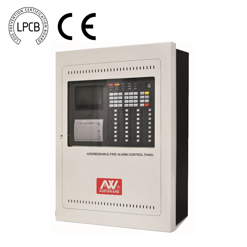
StandardsThe D-TECTRON Fire Alarm System complies with the following UL Standards and NFPA 72, International Building Code (IBC), Fire Alarm System requirements:
UL 864, 10th Edition, UL268\UL521\UL1638\UL1971\UL464\UL38 FM Approval Ongoing
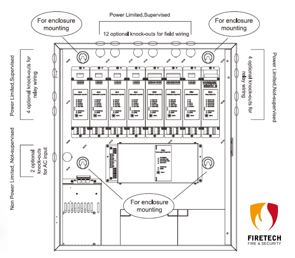
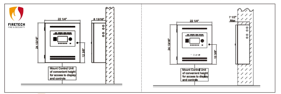
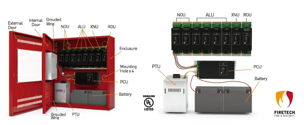
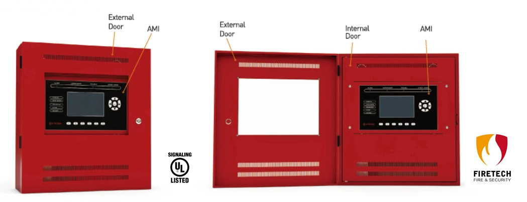
DT106 provides modular assemble style.
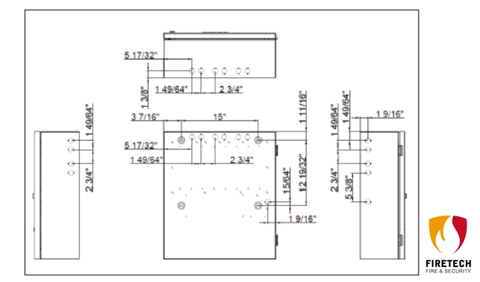
OutsideInsideDT106 Mounting SpaceDT106 Installation SizeWiring & ConfigurationDevice loopThe system provides up to 252 devices addresses per SLC, max. 4 loops of total 1008 devices. The loop circuit is supervised for opens, shorts, and grounds
| Circuit specifications | DT106 |
| Device loops | 1 to 4 Class B or A loop, supporting 252 devices per loop |
| Communication line voltage | SLC output range: 20.4 to 28Vdc. (24 V nominal) |
| Circuit current | 220 mA |
Basic system wiring and detector positioning must be done in accordance with NFPA 72 or other applicable codes and instructions from the appropriate local authority having jurisdiction. Unit connections and limitations are as indicated on the wiring diagrams included in the SYSTEM WIRING section of the manual.
NAC circuitsDT106 Fire Alarm Control Panels is equipped with four notification appliance circuits.
| Specifications | NAC |
| Circuit Type | 2 Class B or A |
| Voltage | 24 VDC nominal |
| Current | 4.0 A total, 2.0 A max. per circuit |
| Impedance | 1.8 V maximum line voltage drop |
| EOLR | 10 K Ω, 1/4 W |
| Synchronization | Supported system-wide |
Notification Appliance Circuit Wiring - Class ANotification Appliance Circuit Wiring - Class BOne EOL (R=10kOhms) is needed at the end of the line to monitor the circuit
integrity.
Relay specifications| | Alarm | Trouble | Supervisory |
| Type | Form C |
| Voltage | 30VDC, 2A |
Relay circuits can only be connected to power-limited sources.
Annunciator loop
The control panel provides a connection for up to four supervised remote annunciators.
Annunciator Wire Selection Guide
| [AWG] | Wire Resistance (Ohms/km) | ft | m |
| 12 | 5.31 | 15443 | 4708 |
| 13 | 6.69 | 12257 | 3737 |
| 14 | 8.45 | 9704 | 2959 |
| 15 | 10.6 | 7736 | 2358 |
| 16 | 13.5 | 6074 | 1852 |
| 17 | 16.3 | 5031 | 1534 |
| 18 | 21.4 | 3832 | 1168 |
Specifications
| | DT106 |
| Device loops | 1to 4 loops, Class A or B, each loop supporting up to 252 device addresses. |
| Notification appliance circuits | 1 to 4 Class B or A
8.0 A DC total
2.0 A DC each max. per circuit |
| Primary power | 110 - 120 VAC, 60 Hz, 3.86 A max. 220 - 240 VAC, 50 Hz, 1.96 A max. |
| Base panel current standby | 333 mA |
| Base panel current alarm | 354 mA |
| Input zones | 64 max. |
| Remote annunciator | Data line length: 15,443 ft. (4,708 m) when using 12 AWG wiring |
| Auxiliary power output circuit | Aux power: 24 VDC nominal at 500 mA (standby), 1.2A (alarm) Note: For a list of compatible devices, see the DT106 manual |
| Loop circuit | Maximum loop resistance: 20 Ω Maximum loop capacitance: 0.1 µF
SLC output range: 20.4 to 26.4Vdc. (24 V nominal)
Operating current (fully loaded loop) Stand by: 100 mA; Alarm: 220 mA Class A and B wiring
Max. resistance between isolators: Limited only by overall wire run lengths |
| Batteries | Type: Sealed lead acid Voltage: 24 VDC (2 x 12 V batteries connected in series) Charging current: 1.756 A; max. Amp hour capacity: 40 Ah; Standby operation: 24 hour Placement: Up to two 40 Ah batteries will fit in the DT106 control panel cabinet. |
| Relays Output | One programmable relay
4 non-programmable status relays Status: Alarm, Supervisory, Trouble, Monitor Form C Contact
Contact Rating: 2A 30VDC
Power Factor Ration:0.35 |
| Notification Appliance Circuits | Total of 4 circuits supported, total power available 8A
2 Class A or 2 Class B circuits on each NOU
Maximum Current: 2A per NAC circuit
Alarm Voltage: 24V nominal
Bell code: Temporal 3
Panel supports one regulated 24 VDC NAC, or four special application 24 VDC NAC. Refer to Table 20 for specific appliances/devices.
Max line loss: 1.8 V. |
| Ground fault impedance | 0 to 6.6 kΩ |
| Alarm contact | Form C 30 VDC at 2 A (pf=0.35) |
| Trouble contact | Form C 30 VDC at 2 A (pf=0.35) |
| Supervisory contact | Form C 30 VDC at 2 A (pf=0.35) |
| Environmental | Temperature: 0 to 49˚C (32 to 120˚F) Relative humidity: 0 to 93% noncondensing |
| Terminal rating | All terminals rated for 12 to 18 AWG (0.75 to 2.5 mm²) |
FIRETECH provides wide-ranging of Addressable/Conventional Fire Alarm Sytstem and products (UL/EN54), Please feel free to contact us for more details if you have any enquiry.

 Complaint