Description
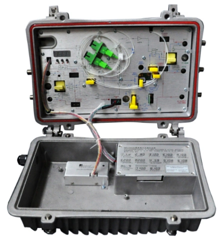
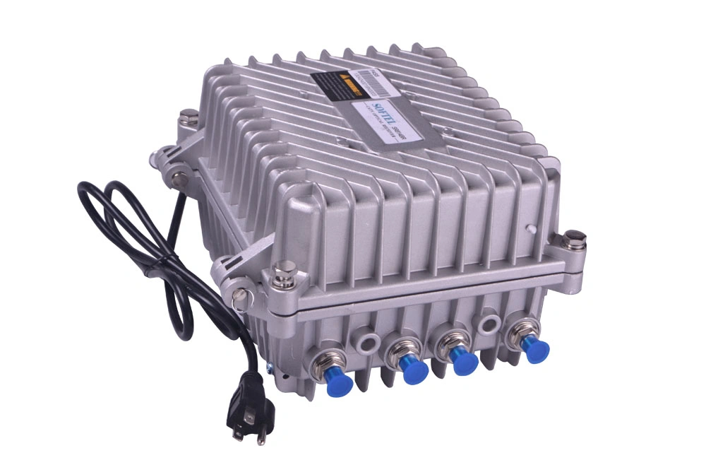
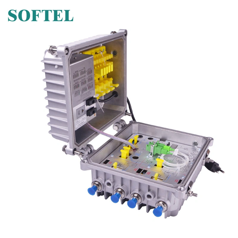
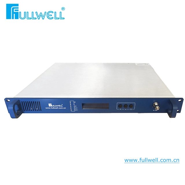
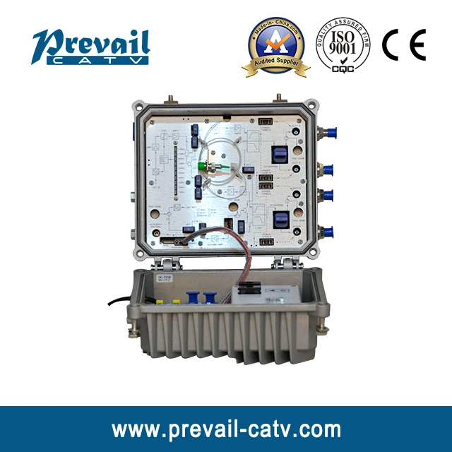
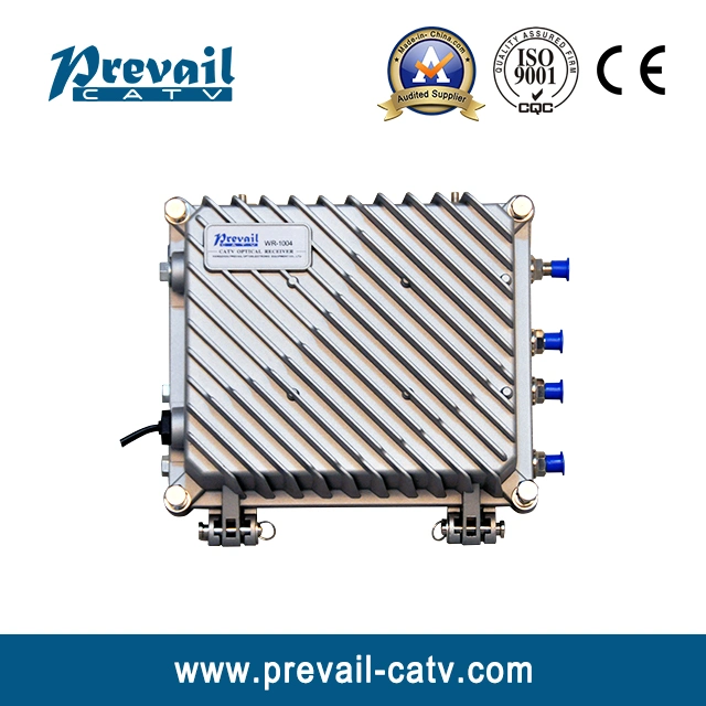
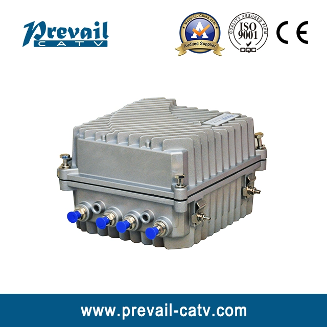
1. Product SummaryWR1004DM-B is our new high-class 4-way output CATV network optical receiver. The pre-amplifier adopts all-GaAs MMIC, post-amplifier adopts GaAs module. Optimized circuit design, coordinate with our 10 years design experience, the device achieve high performance index. The adjustment of RF attenuation and equalization both adopts adjustable attenuator inserter that makes the engineering debug very convenience. It is the main equipment to build CATV network.
2. Performance Characteristics- Optical AGC control, when input optical power is -7~+2dBm, the output level, CTB, CSO basically unchanged.
- 10 bar LED optical power instructions, more accurately display the optical power.
- Optimized circuit design, the pre-stage adopts SMT processing, while post-stage adopts module amplify typical circuit, which make the RF signal linear more prefect.
- The adjustment of RF attenuation and equalization both adopts adjustable attenuator, which make the engineering debug more convenient.
- Power doubler output, high gain and low distortion.
- The forward path adds a high-pass filter, while the return path adds a high-pass filter and a low-pass filter, which effectively extend the NPR dynamic range of uplink.
- Return emission can select burst mode to sharply decrease the noise convergence and reduce the forepart receiver number.
3. Technique Parameter3.1 Link testing conditionsThe performance parameters of this manual according to the measuring method of GY/T 194-2003 <Specifications and methods of measurement on optical node used in CATV systems>, and tested in the following conditions.
Testing conditions:
- Forward optical receive part: with 10km standard optical fiber, passive optical attenuator and standard optical transmitter composed the testing link. Set 59 PAL-D analog TV channel signal at range of 45/87MHz~550MHz under the specified link loss. Transmit digital modulation signal at range of 550MHz~862/1003MHz, the digital modulation signal level (in 8 MHz bandwidth) is 10dB lower than analog signal carrier level. When the input optical power of optical receiver is -1dBm, the RF output level is 108dBμV, with 6dB output tilt, measure the C/CTB, C/CSO and C/N.
- Return optical transmit part: Link flatness and NPR dynamic range are the link indexes which is composed of backward optical transmitter and backward optical receiver.
3.2 Technique Parameters| Item | Unit | Technical Parameters |
| Forward part |
| Optical Parameters |
| Receiving Optical Power | dBm | -7 ~ +2 |
| Optical Return Loss | dB | >45 |
| Optical Receiving Wavelength | nm | 1100 ~ 1600 |
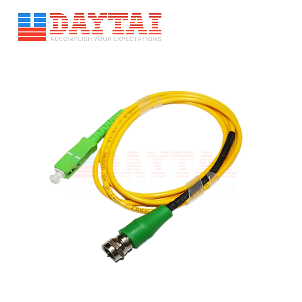
| Optical Connector Type | | FC/APC, SC/APC or specified by the user |
| Fiber Type | | Single Mode |
| Link Performance |
| C/N | dB | ≥ 51 (-1dBm input) |
| C/CTB | dB | ≥ 65 | Output Level 108dBμV
EQ 6dB |
| C/CSO | dB | ≥ 60 |
| RF Parameters |
| Frequency Range | MHz | 45 ~862/1003 (or specified by the user) |
| Flatness in Band | dB | ±0.75 |
| Fixed slope | dB | 2±0.5 |
| Rated Output Level | dBμV | ≥ 108 |
| Max Output Level | dBμV | ≥ 110 |
| Output Return Loss | dB | ≥14 |
| Output Impedance | Ω | 75 |
| ATT | dB | 0~15 |
| EQ | dB | 0~15 |
| Return Part |
| Optical Parameters |
| Optical Transmit Wavelength | nm | 1310±10, 1550±10 or specified by the user |
| Output Optical Power | mW | 0.5, 1, 2 |
| Optical Connector Type | | FC/APC, SC/APC or specified by the user |
| RF Parameters |
| Frequency Range | MHz | 5 ~ 65 (or specified by the user) |
| Flatness in Band | dB | ±1 |
| Input Level | dBμV | 72 ~ 85 |
| Output Impedance | Ω | 75 |
| General Performance |
| Power Voltage | V | A: AC (150~265)V; B: AC (35~90)V |
| Operating Temperature | ºC | -40~60 |
| Storage Temperature | ºC | -40~65 |
| Relative Humidity | % | Max 95% non-condensing |
| Consumption | VA | ≤ 30 |
| Dimension | mm | 240 (L)×240 (W)×150 (H) |
Note: The forward RF parameters are tested under the condition of using NEC module in the last stage. Use other module, the parameters will be slightly different.
| Burst Mode (Select this mode, see below) |
Optical Output Power
(Close the burst mode) | dBm | -30 |
| Laser Turn On Threshold | dBμV | ≥70 |
| Laser Turn Off Threshold | dBμV | ≤62 |
| Laser Turn On Time (t1) | us | 0.5≤ t1 ≤1 |
| Laser Turn Off Time (t2) | us | 0.5≤ t2 ≤1.5 |
contact usProduction Process

 Complaint