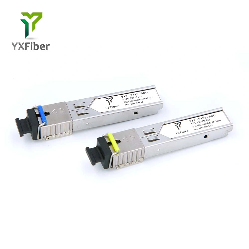
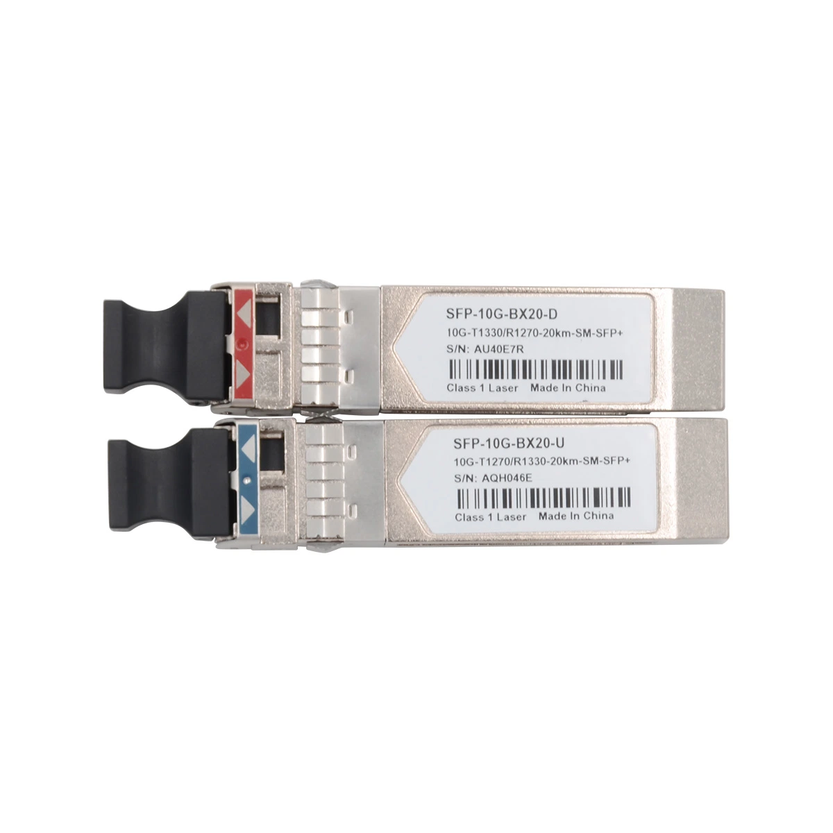
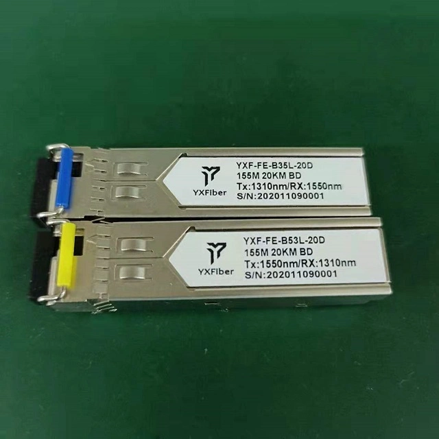
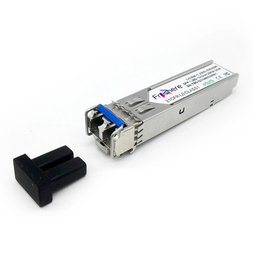
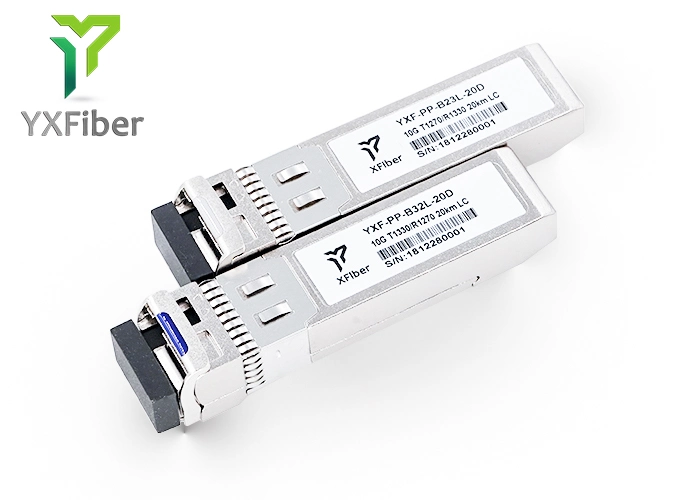
The SFP transceivers are high performance, cost effective modules supporting dual data-rate of 1.25Gbps/1.0625Gbps and 20km transmission distance with SMF.
The transceiver consists of three sections: a FP laser transmitter, a PIN photodiode integrated with a trans-impedance preamplifier (TIA) and MCU control unit. All modules satisfy class I laser safety requirements.
The transceivers are compatible with SFP Multi-Source Agreement (MSA) and SFF-8472. For further information, please refer to SFP MSA.
Absolute Maximum Ratings:
Table 1 - Absolute Maximum Ratings:
| Parameter | Symbol | Min | Max | Unit |
| Supply Voltage | Vcc | -0.5 | 4.5 | V |
| Storage Temperature | Ts | -40 | +85 | °C |
| Operating Humidity | - | 5 | 85 | % |
Recommended Operating Conditions:
Table 2 - Recommended Operating Conditions:
| Parameter | Symbol | Min | Typical | Max | Unit |
| Operating Case Temperature | Standard | Tc | 0 | | +70 | °C |
| -20 | +85 |
| Industrial | -40 | | +85 | °C |
| Power Supply Voltage | Vcc | 3.13 | 3.3 | 3.47 | V |
| Power Supply Current | Icc | | | 300 | mA |
| Data Rate | Gigabit Ethernet | | | 1.25 | | Gbps |
| Fiber Channel | | | 1.063 | |
| | | | | | | | |
Pin Descriptions:
| Pin | Signal Name | Description | Plug Seq. | Notes |
| 1 | VEET | Transmitter Ground | 1 | |
| 2 | TX FAULT | Transmitter Fault Indication | 3 | Note 1 |
| 3 | TX DISABLE | Transmitter Disable | 3 | Note 2 |
| 4 | MOD_DEF(2) | SDA Serial Data Signal | 3 | Note 3 |
| 5 | MOD_DEF(1) | SCL Serial Clock Signal | 3 | Note 3 |
| 6 | MOD_DEF(0) | TTL Low | 3 | Note 3 |
| 7 | Rate Select | Not Connected | 3 | |
| 8 | LOS | Loss of Signal | 3 | Note 4 |
| 9 | VEER | Receiver ground | 1 | |
| 10 | VEER | Receiver ground | 1 | |
| 11 | VEER | Receiver ground | 1 | |
| 12 | RD- | Inv. Received Data Out | 3 | Note 5 |
| 13 | RD+ | Received Data Out | 3 | Note 5 |
| 14 | VEER | Receiver ground | 1 | |
| 15 | VCCR | Receiver Power Supply | 2 | |
| 16 | VCCT | Transmitter Power Supply | 2 | |
| 17 | VEET | Transmitter Ground | 1 | |
| 18 | TD+ | Transmit Data In | 3 | Note 6 |
| 19 | TD- | Inv. Transmit Data In | 3 | Note 6 |
| 20 | VEET | Transmitter Ground | 1 | |
Optical and Electrical Characteristics
DF -3124-L2x(D): (FP and PIN, 1310nm, 20km Reach)
Table 3 - Optical and Electrical Characteristics
| Parameter | Symbol | Min | Typical | Max | Unit | Notes |
| Transmitter |
| Centre Wavelength | λc | 1260 | 1310 | 1360 | nm | |
| Spectral Width (RMS) | λ | | | 4 | nm | |
| Average Output Power | Pout | -9 | | -3 | dBm | 1 |
| Extinction Ratio | ER | 9 | | | dB | |
| Optical Rise/Fall Time (20%~80%) | tr/tf | | | 0.26 | ns | |
| Data Input Swing Differential | VIN | 400 | | 1800 | mV | 2 |
| Input Differential Impedance | ZIN | 90 | 100 | 110 | Ω | |
| TX Disable | Disable | | 2.0 | | Vcc | V | |
| Enable | | 0 | | 0.8 | V | |
| TX Fault | Fault | | 2.0 | | Vcc | V | |
| Normal | | 0 | | 0.8 | V | |
| Receiver |
| Centre Wavelength | λc | 1260 | | 1580 | nm | |
| Receiver Sensitivity | | | | -23 | dBm | 3 |
| Receiver Overload | | 0 | | | dBm | 3 |
| LOS De-Assert | LOSD | | | -24 | dBm | |
| LOS Assert | LOSA | -35 | | | dBm | |
| LOS Hysteresis | | 1 | | 4 | dB | |
| Data Output Swing Differential | Vout | 400 | | 1800 | mV | 4 |
| LOS | High | 2.0 | | Vcc | V | |
| Low | | | 0.8 | V | |
| | | | | | | | | |
Notes:
1. The optical power is launched into SMF.
2. PECL input, internally AC-coupled and terminated.
3. Measured with a PRBS 27-1 test pattern @1250Mbps, BER ≤1×10-12.
4. Internally AC-coupled.
Timing and Electrical:
Table 4 - Timing and Electrical:
| Parameter | Symbol | Min | Typical | Max | Unit |
| Tx Disable Negate Time | t_on | | | 1 | ms |
| Tx Disable Assert Time | t_off | | | 10 | µs |
| Time To Initialize, including Reset of Tx Fault | t_init | | | 300 | ms |
| Tx Fault Assert Time | t_fault | | | 100 | µs |
| Tx Disable To Reset | t_reset | 10 | | | µs |
| LOS Assert Time | t_loss_on | | | 100 | µs |
| LOS De-assert Time | t_loss_off | | | 100 | µs |
| Serial ID Clock Rate | f_serial_clock | | | 400 | KHz |
| MOD_DEF (0:2)-High | VH | 2 | | Vcc | V |
| MOD_DEF (0:2)-Low | VL | | | 0.8 | V |
Diagnostics:
Table 5 - Diagnostics Specification:
| Parameter | Range | Unit | Accuracy | Calibration |
| Temperature | 0 to +70 | °C | ±3°C | Internal / External |
| -40 to +85 |
| Voltage | 3.0 to 3.6 | V | ±3% | Internal / External |
| Bias Current | 0 to 100 | mA | ±10% | Internal / External |
| TX Power | -9 to -3 | dBm | ±3dB | Internal / External |
| RX Power | -23 to 0 | dBm | ±3dB | Internal / External |
Digital Diagnostic Memory Map:
The transceivers provide serial ID memory contents and diagnostic information about the present operating conditions by the 2-wire serial interface (SCL, SDA).
The diagnostic information with internal calibration or external calibration all are implemented, including received power monitoring, transmitted power monitoring, bias current monitoring, supply voltage monitoring and temperature monitoring.
The digital diagnostic memory map specific data field defines as following:
Pin Definitions:
Pin Diagram
Notes:
Plug Seq.: Pin engagement sequence during hot plugging.
1) TX Fault is an open collector output, which should be pulled up with a 4.7k~10kΩ resistor on the host board to a voltage between 2.0V and Vcc+0.3V. Logic 0 indicates normal operation; Logic 1 indicates a laser fault of some kind. In the low state, the output will be pulled to less than 0.8V.
2) TX Disable is an input that is used to shut down the transmitter optical output. It is pulled up within the module with a 4.7k~10kΩ resistor. Its states are:
Low (0 to 0.8V): Transmitter on
(>0.8V, < 2.0V): Undefined
High (2.0 to 3.465V): Transmitter Disabled
Open: Transmitter Disabled
3) Mod-Def 0,1,2. These are the module definition pins. They should be pulled up with a 4.7k~10kΩ resistor on the host board. The pull-up voltage shall be VccT or VccR.
Mod-Def 0 is grounded by the module to indicate that the module is present
Mod-Def 1 is the clock line of two wire serial interface for serial ID
Mod-Def 2 is the data line of two wire serial interface for serial ID
4) LOS is an open collector output, which should be pulled up with a 4.7k~10kΩ resistor. Pull up voltage between 2.0V and Vcc+0.3V. Logic 1 indicates loss of signal; Logic 0 indicates normal operation. In the low state, the output will be pulled to less than 0.8V.
5) RD-/+: These are the differential receiver outputs. They are internally AC-coupled 100 differential lines which should be terminated with 100Ω (differential) at the user SERDES.
6) TD-/+: These are the differential transmitter inputs. They are internally AC-coupled, differential lines with 100Ω differential termination inside the module.
Recommended Interface Circuit:
Mechanical Dimensions:
Ordering information:
| Part Number | Product Description |
| DF-3124-L2C | 1310nm, 1.25Gbps, 20km, 0ºC ~ +70ºC |
| DF-3124-L2CD | 1310nm, 1.25Gbps, 20km, 0ºC ~ +70ºC, With Digital Diagnostic Monitoring |
| DF-3124-L2N | 1310nm, 1.25Gbps, 20km, -20ºC ~ +85ºC |
| DF-3124-L2ND | 1310nm, 1.25Gbps, 20km, -20ºC ~ +85ºC, With Digital Diagnostic Monitoring |
| DF-3124-L2T | 1310nm, 1.25Gbps, 20km, -40ºC ~ +85ºC |
| DF-3124-L2TD | 1310nm, 1.25Gbps, 20km, -40ºC ~ +85ºC, With Digital Diagnostic Monitoring |
Why choose Takfly ?
Service:
1.Customer's logo: Acceptable
2.General inspection on fixing before packing
3.Third party inspection: Acceptable
Quality Control:
All products must go through five checks before manufacturing process
1.Material incoming inspection before production
2.Full check after every individual process finished
3.Full check after production half-done
4.Full check before packing
5.Spots check after production packed before shipping
Advantage:
1.15 years experience in manufacturing fiber optic products..
2.Availability of R & D with more than 10 engineers.
3.Available of design and making mold with special molding house.
4.High quality, attractive price and fast delivery(2-7days)
5.OEM, ODM customer designs are also welcomed
6.More than 200 worker
7.Excellent service
Delivery:
1.Packing: Plastic bag& carton, Neutral packing or as your required.
2.Sample time: 1-3 days after confirmation.
3.Order lead time: 2-7working days depend on quantity and products.
4.Shipping port: Shenzhen, HK or other ports as you required.
5.Shipping term: EXW or FOB
Shipping:
1.Once confirmed the order, and payment sent after finishing goods.
2.Goods will be sent within 7 days with the fast, reasonable and efficient shipping mode such as DHL, EMS, UPS,FEDEX, TNT, etc.
3.Please make sure your postal address is correct. Any lost and mistakes because of wrong address.


 Complaint