Complaint

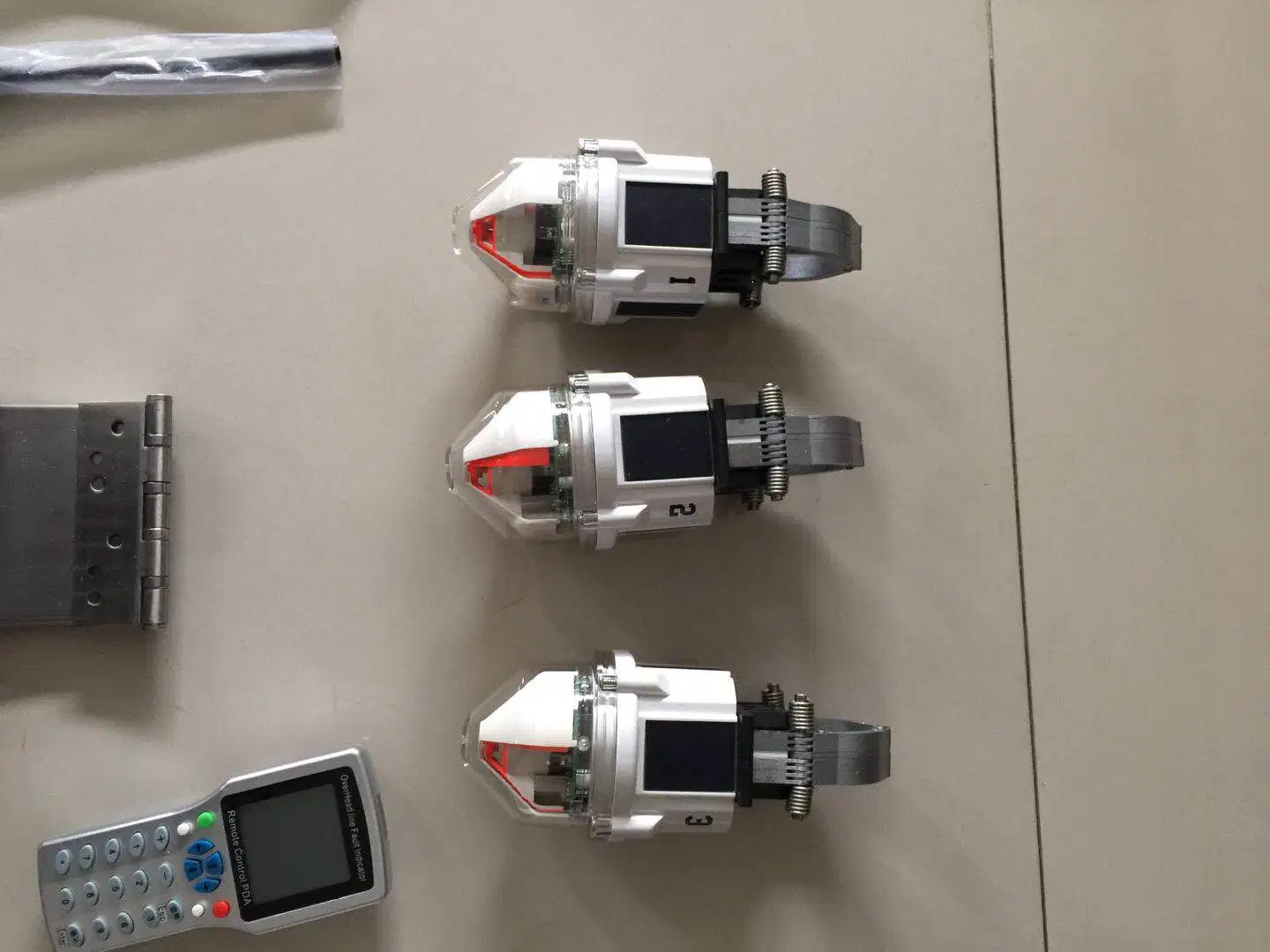
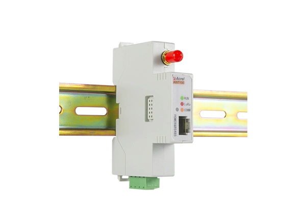
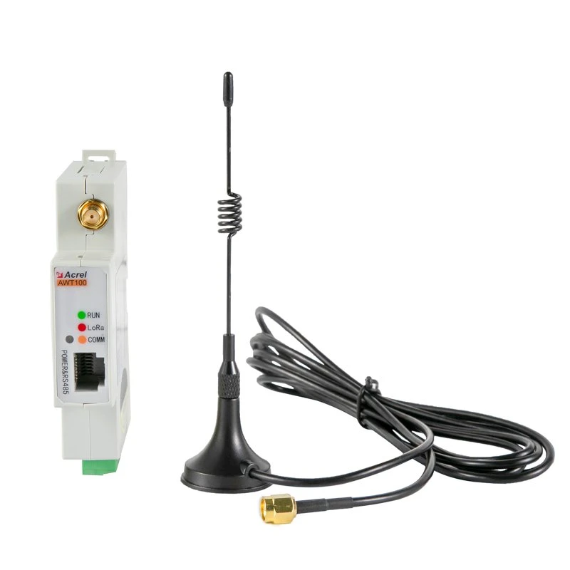
The wireless communication terminal of ESI-309 overhead fault indicator is mainly used to realize the communication between overhead fault indicator and remote server. As a communication bridge between fault indicator and remote server, ESI-309 wireless communication terminal is always in working state. On the one hand, it waits for fault indicator to upload data, on the other hand, it maintains real-time communication with remote server, and uploads all data information to remote server. ESI-309 wireless communication terminal uses 6.2 V rechargeable lithium iron phosphate battery as power source. The power comes from external solar panels.
1) GPRS wireless communication unit;
2) A SIM card holder;
3) 433M wireless communication unit;
4) MCU central processing unit (32-bit ARM as the central processing unit, running speed up to 72Mhz);
5) Real time clock unit;
1) Receiving the data uploaded from the fault indicator in real time;
2) Fault current monitoring and fault diagnosis;
3) Store the operation parameters of the fault indicator, which can be downloaded in the fault indicator when update is needed;
4) To Processing transformation, store and manage the data uploaded from the fault indicator;
5) Real time communication with remote servers, uploading the latest data of the fault indicator to the server;
6) Support remote online upgrade and local serial port upgrades;
7) The standard transport protocol set IEC60870-5-101 (supports 101 of the various length configuration);
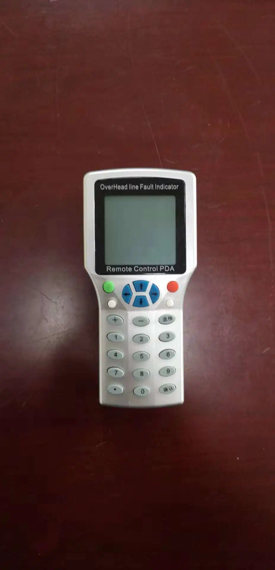
8) Support handheld PDA app - 800 for its on-site settings;
9) Support the free configuration of upload point table (direct parameter configuration does not need to modify the program);
10) The current status of the terminal can be observed remotely through the super bright indicator lamp;
11) Both solar panels and terminals are connected by means of Navigation;
12) The 18V30W solar panel is used to charge 6V17ah lithium iron phosphate battery;
13) The terminal can support 10 sets of fault indicator access;
14) Support remote reset and remove fault flag;
15) Setting parameters through SMS mode;
16) PC configures its parameters through 232;
17) Support 485 communication mode;
18) Support Netcom 4G communication mode;
19) Support GPS system positioning;
20) Waterproof grade IP65;
21) Compact size and easy installation;
a)
a) Technical parameters of wireless module
1) Working frequency: 433.00 ~ 491.00MHz Modulation mode: FSK
2) Frequency stability: 10PPM Transmitting power...…......5mW
3) Receiving sensitivity….....…. -114dBm.........….........…Air Baud rate...............20kbps
4) Signal transmission distance..................…>50m
a) GSM module technical parameters
1) Working frequency.........…. GSM850/EGSM900/DCS1800/PCS1900
2) Maximum output power......…. GSM850/EGSM900: Class 4(2W)
.......…. DCS1800/PCS1900: Class 1(1W)
3) Receiving signal sensitivity......<-106dBm Antenna: 50Ω
4) GPRS......…...Class 12...…. Mobile base station......…...Class B
5) Data storage unit (4Mb SPI storage); charging management unit;;
6) A GSM antenna interface;
7) A 6V battery interface;
8) An external 9-28V charging interface (external power supply or solar panel can be connected).
9) Two 232 voltage 232 interfaces; (for parameter setting and upgrade)
b) Other Technical Parameters
1) Working Current......….......<50Ma...…...supply voltage......6.2VDC
2) Battery Specification............6V 17AH(Lithium iron phosphate)
3) Solar panel Specifications.........18V 26W
4) Working Temperature Range...…. -35ºC ~ 75ºC