Description
Product Features
- Supports 9.95 to 11.3Gb/s bit rates
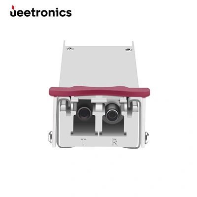
- Simplex LC Connector
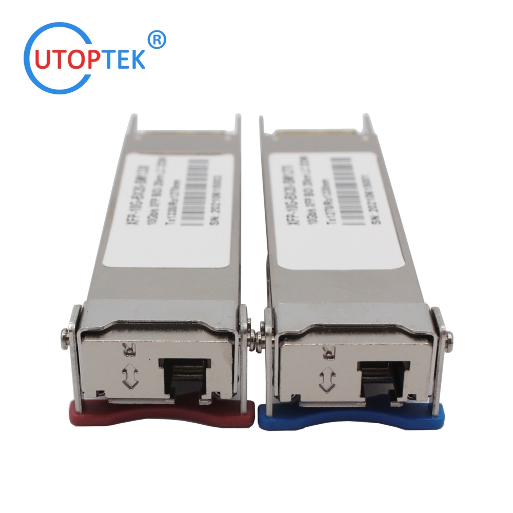
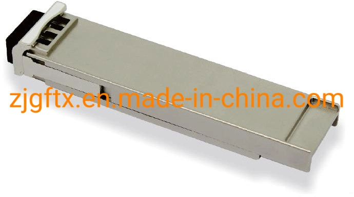
- Hot-pluggable XFP footprint
- Full C-band tunable transmitter and APD receiver
- 50GHz ITU Grid, C-Band(1528.77~1563.86nm)
- Applicable for 80km SMF connection
- Low power consumption, < 3.5W
- Digital Diagnostic Monitor Interface
- Operating case temperature: Commerical:0 to 70 °C
Applications
- DWDM 10G SONET/SDH
- DWDM, IEEE 10GBASE-ZR based Ethernet
- ITU G.709 / OTN FEC applications
- Other optical link
Product Descriptions
GFC-OLTDXX1XL-CD80 is tunable XFP Transceiver exhibits excellent wavelength stability, supporting operation at 100GHz channel, cost effective module. It is designed for 10G tunable SDH 10GBASE-ZR and 10G Fiber- Channel applications. The transceiver consists of two sections: The transmitter section incorporates a tunable EML laser. And the receiver section consists of a APD photodiode integrated with a TIA. All modules satisfy class I laser safety requirements. The tunable XFP transceiver provides an enhanced monitoring interface, which allows real-time access to device operating parameters such as transceiver temperature, laser bias current, transmitted optical power, received optical power and transceiver supply voltage. Functional Diagram
Absolute Maximum Ratings | Parameter | Symbol | Min. | Max. | Unit | Note |
Supply Voltage | Vcc3 | -0.3 | 3.63 | V | |
| Vcc2 | -0.3 | 1.98 | V | |
| Vcc5 | -0.5 | 6 | V | |
| Storage Temperature | TS | -40 | 85 | °C | |
| Relative Humidity | RH | 0 | 85 | % | |
Note: Stress in excess of the maximum absolute ratings can cause permanent damage to the transceiver. General Operating Characteristics
| Parameter | Symbol | Min. | Typ | Max. | Unit | Note |
| Data Rate | DR | 9.95 | 10.3125 | 11.3 | Gb/s | |
Supply Voltage | Vcc3 | 3.13 | 3.3 | 3.47 | V | |
| Vcc2 | 1.71 | 1.8 | 1.98 | V | |
| Vcc5 | 4.75 | 5 | 5.25 | V | |
Supply Current | Icc3 | | | 750 | mA | |
| Icc2 | | | 500 | mA | |
| Icc5 | | | 1000 | mA | |
| Operating Case Temp. | Tc | 0 | | 70 | °C | |
Electrical Characteristics (TOP(C) = 0 to 70 ºC, VCC = 3.13 to 3.47 V) | Parameter | Symbol | Min. | Typ | Max. | Unit | Note |
| Transmitter |
| Differential data input swing | VIN,PP | 120 | | 820 | mVpp | 1 |
| Transmit Disable Voltage | VD | 2.0 | | Vcc | V | |
| Transmit Enable Voltage | VEN | Vee | | Vee+0.8 |
| Input differential impedance | Rin | | 100 | | Ω | |
| Receiver |
| Differential data output swing | Vout,pp | 300 | | 850 | mVpp | 2 |
| Output rise time and fall time | Tr, Tf | 28 | | | Ps | 3 |
| LOS asserted | VLOS_F | VCC-0.8 | | Vcc | V | 4 |
| LOS de-asserted | VLOS_N | Vee | | Vee+0.8 | V | 4 |
Notes:- Connected directly to TX data input pins. AC coupling from pins into laser driver IC.
- Into 100 differential termination.
- 20 - 80%. Measured with Module Compliance Test Board and OMA test pattern. Use of four 1's and four 0's sequence in the PRBS 9 is an acceptable alternative.
- LOS is an open collector output. Should be pulled up with 4.7k - 10k on the host board. Normal operation is logic 0; loss of signal is logic 1.
Optical Characteristics (TOP(C) = 0 to 70 ºC, TOP(I) =-40 to 80 ºC,VCC = 3.13 to 3.47 V) | Parameter | Symbol | Min. | Typ | Max. | Unit | Note |
| Transmitter |
| Operating Wavelength | λc | 1528.384 | | 1568.773 | nm | |
| Center Wavelength (End of Life) | λc_EOL | | λc±25pm | | | |
| Ave. output power (Enabled) | PAVE | -1 | | 3 | dBm | 1 |
| Side-Mode Suppression Ratio | SMSR | 30 | | | dB | |
| Extinction Ratio | ER | 9 | | | dB | |
| Relative Intensity Noise | RIN | | | -128 | dB/Hz | |
| Output Optical Eye | IEEE 802.3-2005 Compliant |
| Receiver |
| Operating Wavelength | λ | 1528.384 | | 1568.773 | nm | |
| Receiver Sensitivity | PSEN1 | | | -23 | dBm | 2 |
| Overload | PAVE | | | -7 | dBm | |
| LOS Assert | Pa | -35 | | | dBm | |
| LOS De-assert | Pd | | | -24 | dBm | |
| LOS Hysteresis | Pd-Pa | 0.5 | | | dB | |
Notes:- Average power figures are informative only, per IEEE 802.3ae.
- Measured with worst ER=9; BER<10-12; 231 - 1 PRBS.
Management Interface
The transceivers provide serial ID memory contents and diagnostic information about the present operating conditions by the 2-wire serial interface (SCL, SDA).
The Module provides diagnostic information about the present operating conditions. The transceiver generates this diagnostic data by digitization of internal analog signals Alarm/warning threshold data is written during device manufacture. Received power monitoring, transmitted power monitoring, bias current monitoring, supply voltage monitoring and temperature monitoring all are implemented.
The digital diagnostic memory map specific data field defines as following.
TYPICAL INTERFACE CIRCUIT
Package Dimensions


 Complaint