
 Complaint

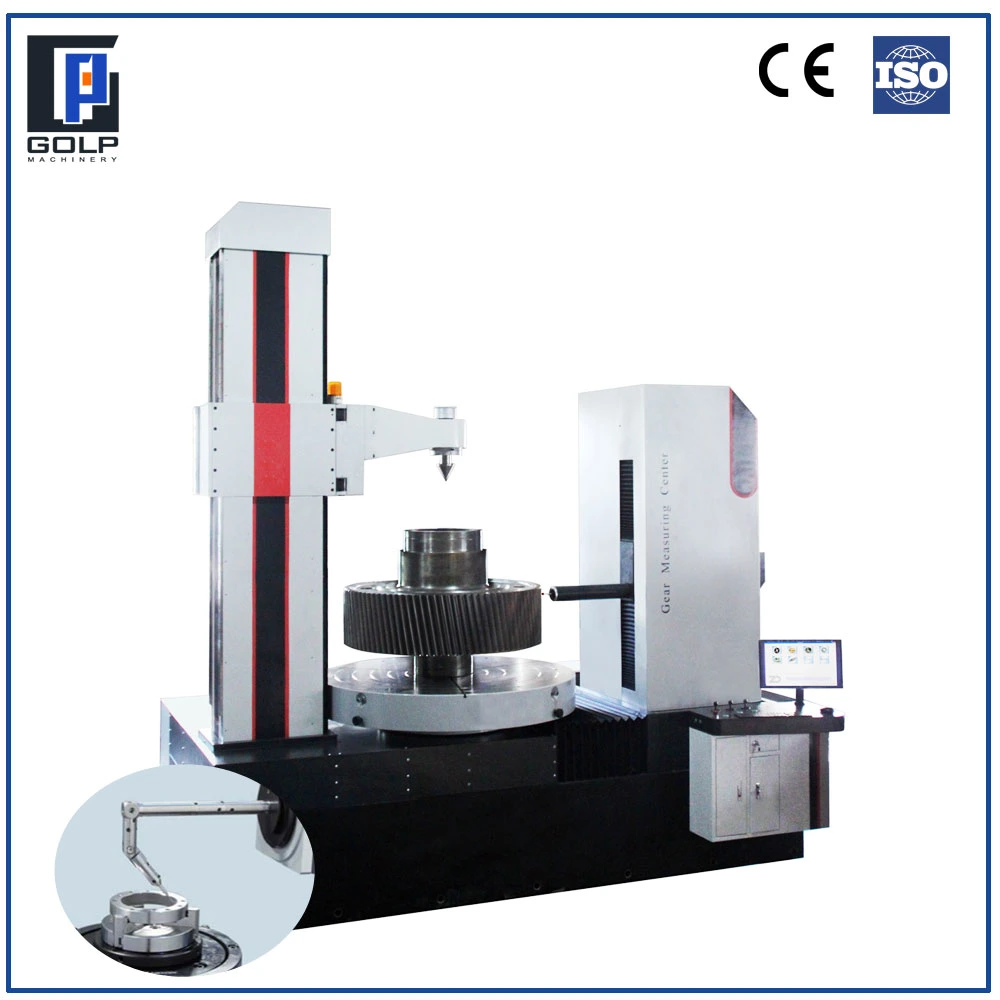
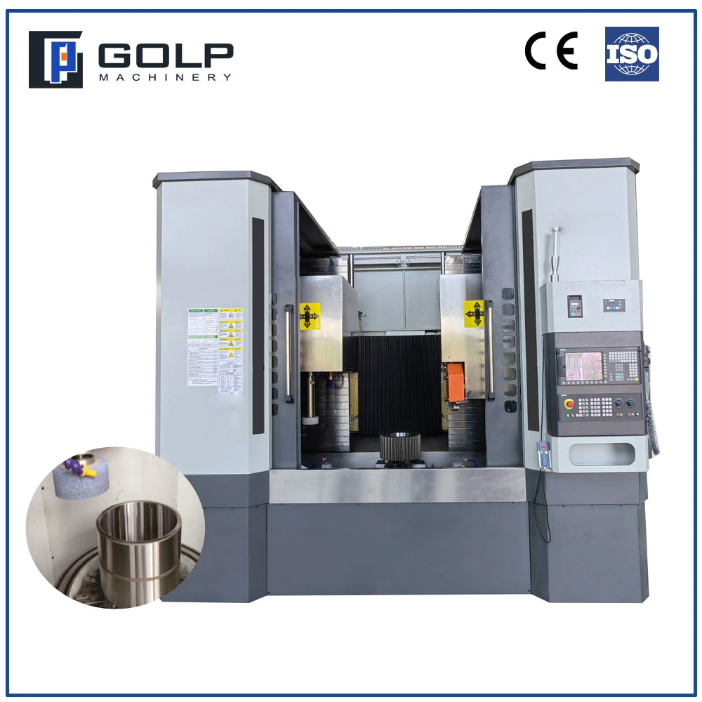
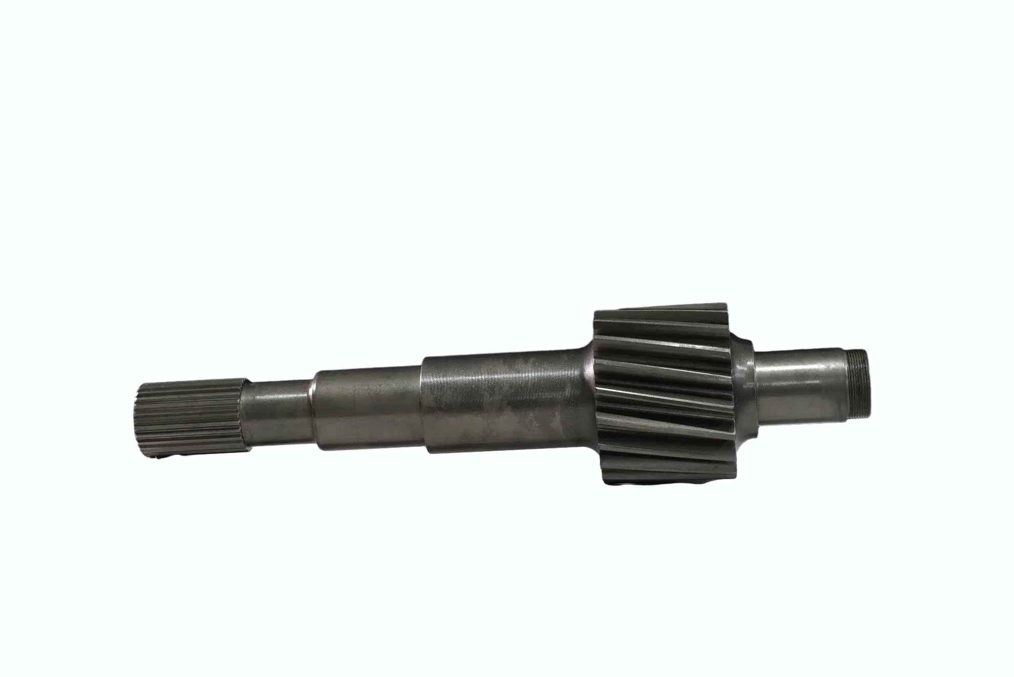
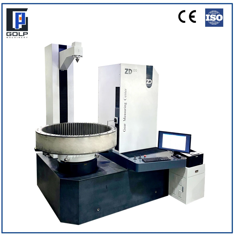
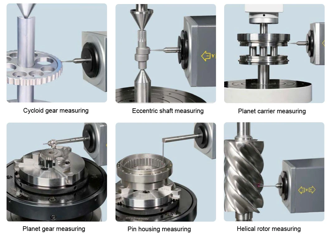
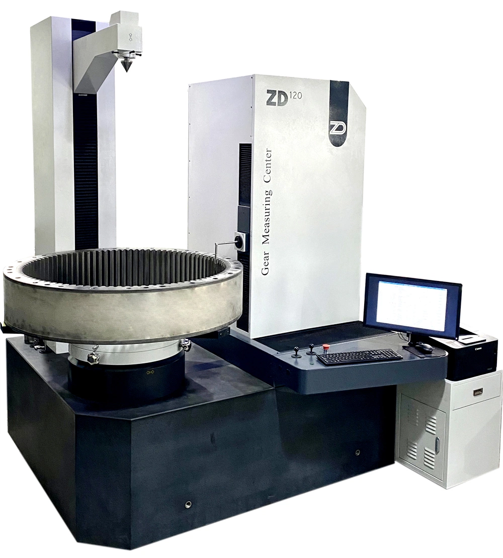
ZD series gear measuring center is a novel series improved fromthe original JD series, approaching the advanced world level. It adopts 4-axis (X, Y,Z, C) measuring principle, a naturalgranite base, an integrated layout, a quasi-3D digital scanning probe, a stylus management system based on magnetic adapters,(all-axis)full closed-loop control technologies, hierarchical CNC control techniques, high precision optical encoders, DDR and servo motors,precision roller quides, ball screw transmissions, computerized data acquisition and processing technologies etc. The instrument can automatically and precisely measure profile deviations, helix deviations, pitch deviations, cumulative pitch deviations, runout and other items of involute cylindrical gears (gear clusters, internal gears etc.), gear cutters (hobs, shaping cutters, shaving cutters etc.), worms, worm wheels, spiral (straight) bevel gears etc. Furthermore, it supports extensions such as measuring camshafts, cylinder equipartition deoree and scan tooth contours. ZD series gear measuring center leads the development direction of gear measuring instruments. |
| TECHNICAL FEATURES Δ Stable host system: The instrument consists of a natural granite (or precise cast iron) base; a CNCrotary axis (C) with a DDR motor, precision ball bearing and high-resolution optical encoders; three linear axes(X,Y, Z) with AC servo drive units, ball screw transmissions, THK and linear roller guides and precision linearoptical encoders; a workpiece guide with a precision linear guide. The tail stock(G axis) utilizes ball screwtransmission and is driven by an AC servo motor. It automatically stops when reaching the measuring position. Δ Advanced digital scanning probe system: We have technology for the quasi-3D digital probe system. The probe system supports measurements simultaneously using any two measuring directions(XY,XZ, YZ). Measurements simultaneously using all three measuring directions(X,Y,Z)are not supported. The probe system uses precision optical encoders (RENISHAW) in measuring directions, offering stable signals against interference. The stylus has a 3-point magnetic adapter for fixation, enabling easy stylus replacements and offering high positioning repeatability. There are electronic limits and mechanical out-of-limit protections in X/Y/Z-directions. Additionally, the probe can be locked separately or combined in X/Y/Z-directions. The probe system satisfies various requirements in gear and gear cutter measuring. Δ International stylus management system: The instrument adopts a stylus management system used worldwide on high-end gear measuring centers. Every stylus and measuring rod are pre-calibrated for distortion corrections. The tangential, vertical and radial calibration data are automatically saved, avoiding needs for frequent re-calibrations. Styli can be replaced through their 3-point magnetic adapters. The stylus management system is integrated and offers precautionary information. Δ Reliable encoders as positioning references: HEIDENHAIN(Germany) and RENISHAW(UK) encoders with high accuracy and stability are adopted as positioning references, offering high measuring precision, stability and reliability. Δ Precise control and data acquisition system: With IMAC LX(Delta Tau, USA) controllers based on PMAC technologies, the control system is (all-axis) full closed-loop. All linear axes utilize AC servo motors. The rotary axis utilizes a direct drive rotary (DDR) motor. The coordination of IMAC LX controllers and DDL, AC servomotors enables (all-axis) full closed-loop control and complete data acquisition on measuring positions. All measuring actions are completed automatically. Δ Unique hierarchical control techniques: The instrument adopts hierarchical control techniques. All movements with high real-time requirements are accomplished in the lower control layer, while data acquisition,calculation, processing, display and printing are accomplished with a computer in the upper control layer. Such work division enhances the reliability, efficiency and measuring speed of the instrument, offering possibilities for any measuring process. |
| Model | ZD20 | ZD30 | ZD40 | ZD50 | ZD60 | ZD80 | ZD100 | ZD150 |
| Module(mm) | 0.2-15 | 0.2-15 | 0.3-20 | 0.3-20 | 0.3-25 | 0.5-25 | 0.5-25 | 0.5-35 |
| Max.outer diameter(mm) | 250 | 350 | 450 | 550 | 650 | 850 | 1050 | 1550 |
| Max.verical measuring distance(mm) | 280 | 350 | 380 | 380 | 450 | 600 | 600 | 1000 |
| Max. rolling length(mm) | ±70 | ±90 | ±120 | ±140 | ±180 | ±230 | ±280 | ±300 |
| Distance between centers (mm) | 10-500 | 10-650 | 10-1000 | 10-1000 | 10-1000 | 10-1200 | 10-1200 | 10-2000 |
| Helix angle(°) | 0ºC-90ºC | |||||||
| Max permissible workpiece weight(KG) | 80 | 200 | 300 | 500 | 500 | 800 | 2000 | 8000 |
| Accuracy(um/300mm) | 1.0 | |||||||
| Repeatability(um) | +/-1 | |||||||
| Probe resolution(um) | 0.1 | |||||||
| Item | Z20 | Z30 | Z40 | Z50 | Z60 | Z80 | Z100 | Z150 |
| L(mm) | 1350 | 1350 | 1700 | 1700 | 1800 | 2150 | 2150 | 3750 |
| W(mm) | 1485 | 1485 | 1710 | 1710 | 1870 | 2080 | 2200 | 2520 |
| H(mm) | 1820 | 1820 | 2250 | 2250 | 2250 | 2630 | 2600 | 4000 |
| L1(mm) | 900 | 900 | 1250 | 1250 | 1350 | 1700 | 1900 | 3750 |
| W1(mm) | 910 | 910 | 1140 | 1140 | 1300 | 1500 | 1600 | 2070 |
| H1(mm) | 775 | 775 | 780 | 780 | 810 | 820 | 865 | 800 |
| N.W.(T) | 3.5 | 3.5 | 4.5 | 4.5 | 5 | 7 | 7 | 20 |
| G.W.(T) | 4 | 4 | 5 | 5 | 5.5 | 8 | 8 | 21.5 |
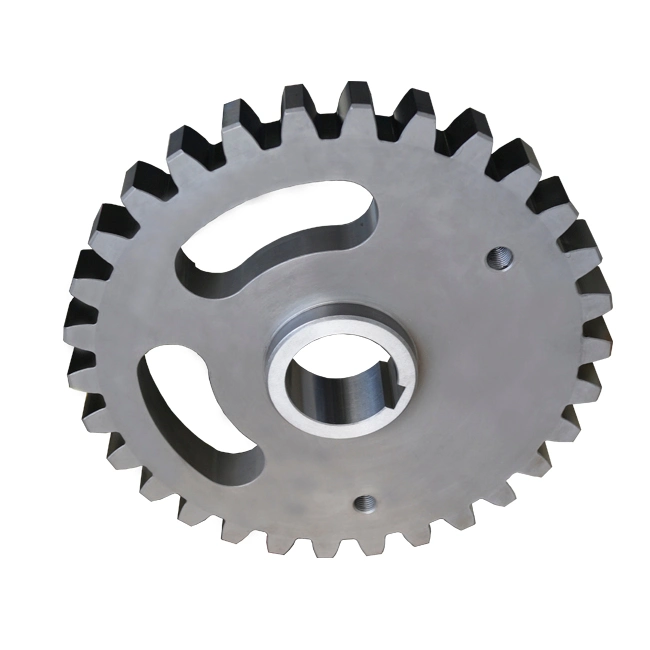
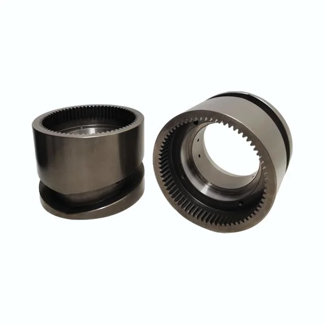
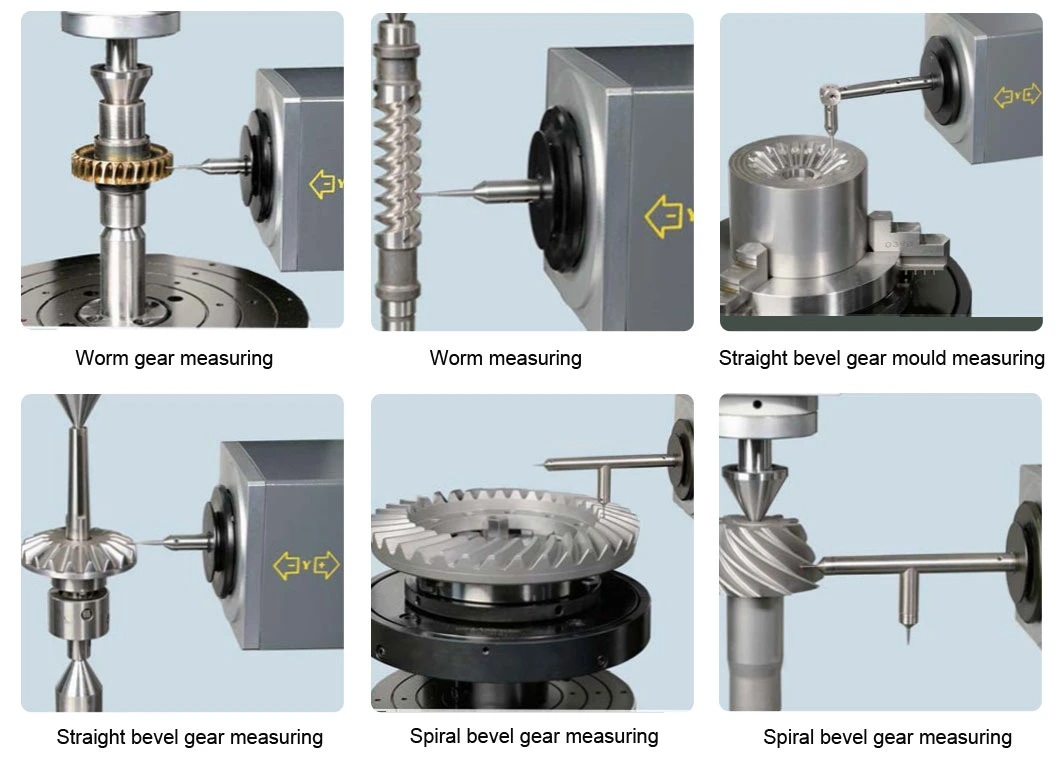
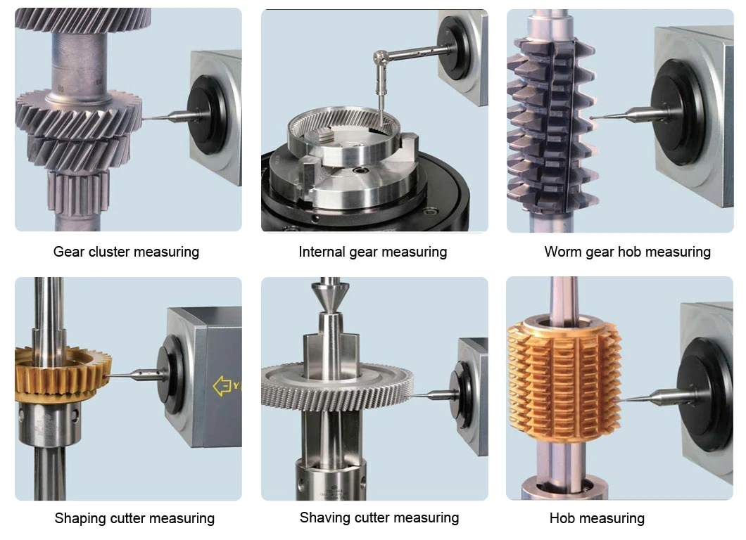
Δ Cylindrical gear: Tooth profile (Fα, ffα, fHα, Cα), helix (F β, ffβ, fH β, C β), pitch (Fp, fp, Fr) Δ Spline (internal and external): Involute spline, Line Spline (triangle.rectangle), Circle Spline and broach. Δ Gear cluster : Automatic circular measurement of multiple gears on one spindle Δ Worm gear and worm Δ Rack Δ Spiral bevel gear and straight bevel gear Δ Other cutter: Spiral gear milling cutter, rack milling cutter, worm milling cutter |