 Complaint

Sine wave control, constant current mode, speed regulation with potentiometer;
High torque, high speed output, maximum speed up to 8000rpm / min; with en (enable), dir (direction), X1 (brake) signal control terminal;
It can output speed measuring pulse FG (gate output);
It can output alarm signal for user detection;
With over-voltage, under voltage, motor locked rotor and other protection functions
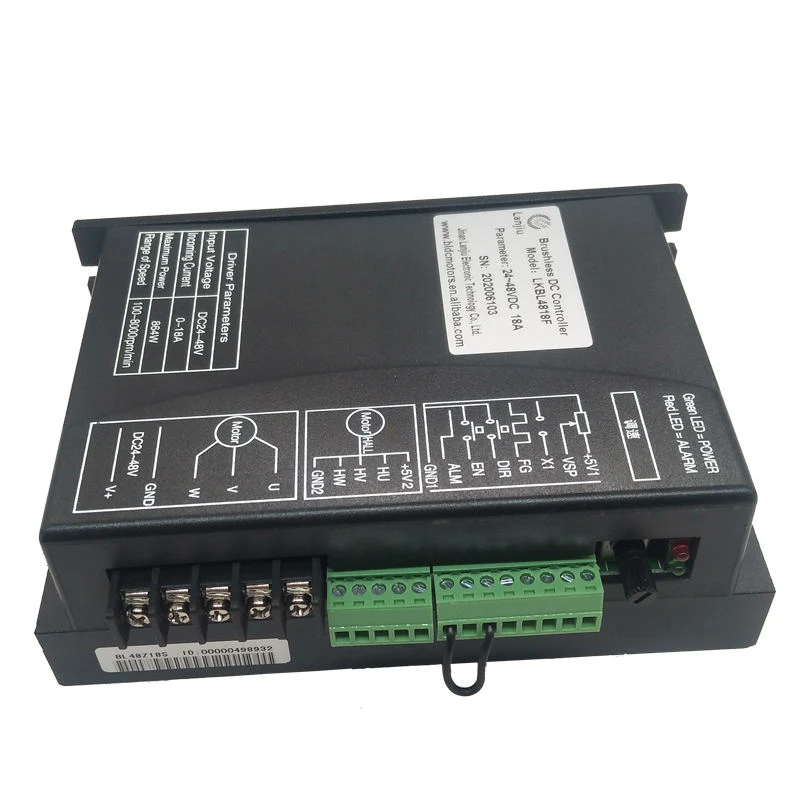
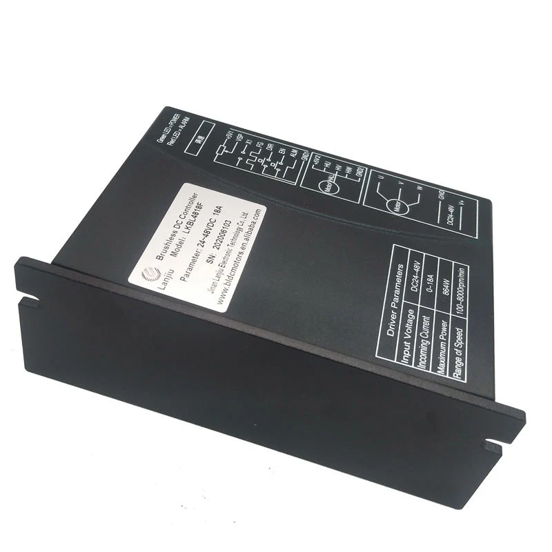
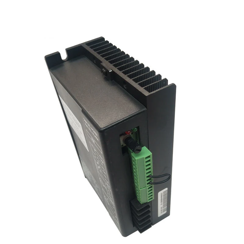
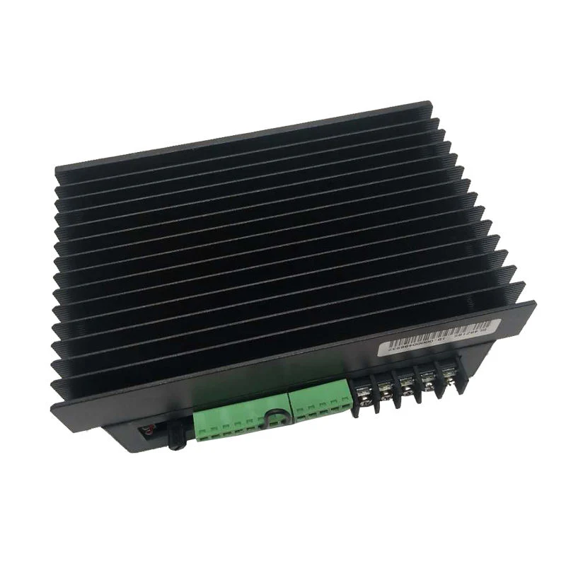
LK-bl48z18s This DC brushless motor driver is the latest high-tech product in the field of small power brushless motor drive launched by our company. product uses large-scale integrated circuit to replace the original hardware design, with higher anti-interference and fast response ability. This product is suitable for driving any low-voltage sine wave hall three-phase DC brushless motor with peak current below 18a and power supply voltage within DC15V ~ 56V (panel nominal DC24V ~ 48V), and has the characteristics of low temperature under high current operation. The products are used in a series of electric automation control fields such as knitting equipment, medical equipment, food packaging machinery, electric tools, etc.
POWER | DC24V~48V |
RATED CURRENT | 18A
|
RATED POWER | MAX 860W |
SUITABLE | ≤650W |
Insulation resistance. | 500MΩ |
Insulation strength | 0.5KV,1 MINS |
Cooling method | Natural air cooling & forced air cooling | |
Environment | Condition | Avoid dust, oil mist and corrosive gases |
Temperature | 0ºC~+50ºC | |
Humidity | 80%RH,no condensation, no frost | |
Vibration | 0.5G(4.9m/s2 )10Hz-60Hz (non-continuous operation) | |
Reserved temperature | -20ºC~+65ºC | |
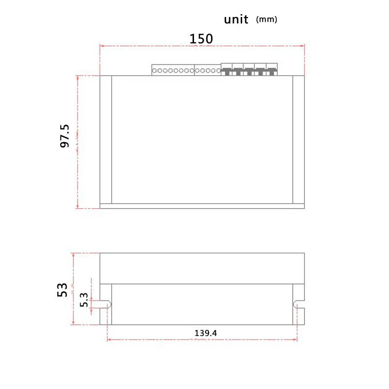
Size | 150mmX97.5mmX53mm | |
Weight | About 0.55Kg | |
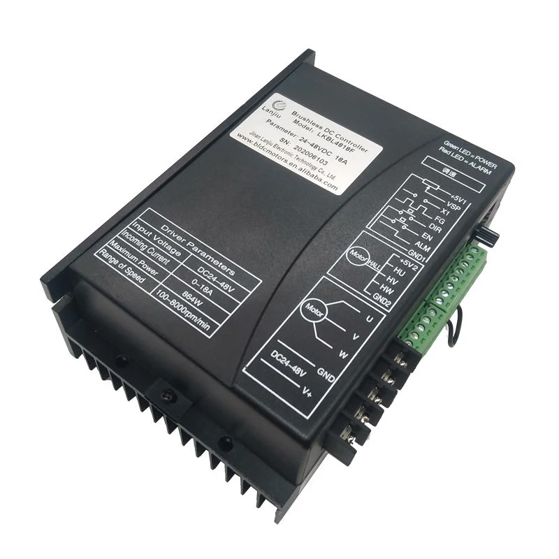
Terminal interface description
Function | Mark | Description |
Indicator light | POWER | If the green power indicator is lighten, it shows that power is normal. |
| ALM | Red status indicator (1) The red light goes out normally; (2) The red light is always on when en is not connected to GND1; (3) When the motor Hall fails, the red light flashes for 1 time and stops for 1 s; (4) Under voltage (power supply voltage < 15V), the red light flashes for 2 times and stops for 1s; (5) In case of over-voltage (power supply voltage > 56V), the red light flashes for 3 times and stops for 1s; (6) When the motor is locked, the red light flashes for 5 times and stops for 1s; Note: in case of over-voltage and under voltage protection of the driver, adjust the voltage to the normal working voltage, and the driver will automatically remove the protection. |
Speed control | Speed control | Equipped with potentiometer to change VSP terminal voltage to achieve 0 ~ 100% speed regulation, range 0 ~ 5V |
Control signal port | +5V1 | Control signal power+( inner power output ) |
| VSP | External speed control signal Control way: By connecting with a potentiometer to change VSP, then it can complete 0 ~ 100% speed adjustment. The range is 0-5V |
| X1 | Input signal, brake on low level or to GND1, the red light keep off(Brake braking force can be adjusted by customer's requirement),When X1 is connected with +5V1 or without any port , motor keeps running. |
| FG | Motor speed pulse output is measuring the frequency of this signal. Then converts it into the actual motor speed. |
| DIR | Rotary direction is controlled by high and low electrical level, motor forward: connected with GND1, motor reversal (anticlockwise) ;without GND1 or connected with +5V, motor forward (clockwise) |
| EN | Connected EN with GND1, motor can work(online status);without connected or high electrical lever, motor can not work(offline status and the red light keep working) |
| ALM | It is signal transfer output. When the power is in danger, the current flow is slow. |
| GND1 | Control signal's power supply |
Hall control port | +5V2 | + motor's Hall power |
| HU | Hall sensor signal U phase input |
| HV | Hall sensor signal V phase input |
| HW | Hall sensor signal W phase input |
| GND2 | The motor's Hall power supply |
The motor and power | U,V,W | The motor's three-phase output signal |
| GND,V+ | GND,V+ stand for direct current flow. The input power is DC18V~50V.(boards show DC24V-48V) |