


 Complaint

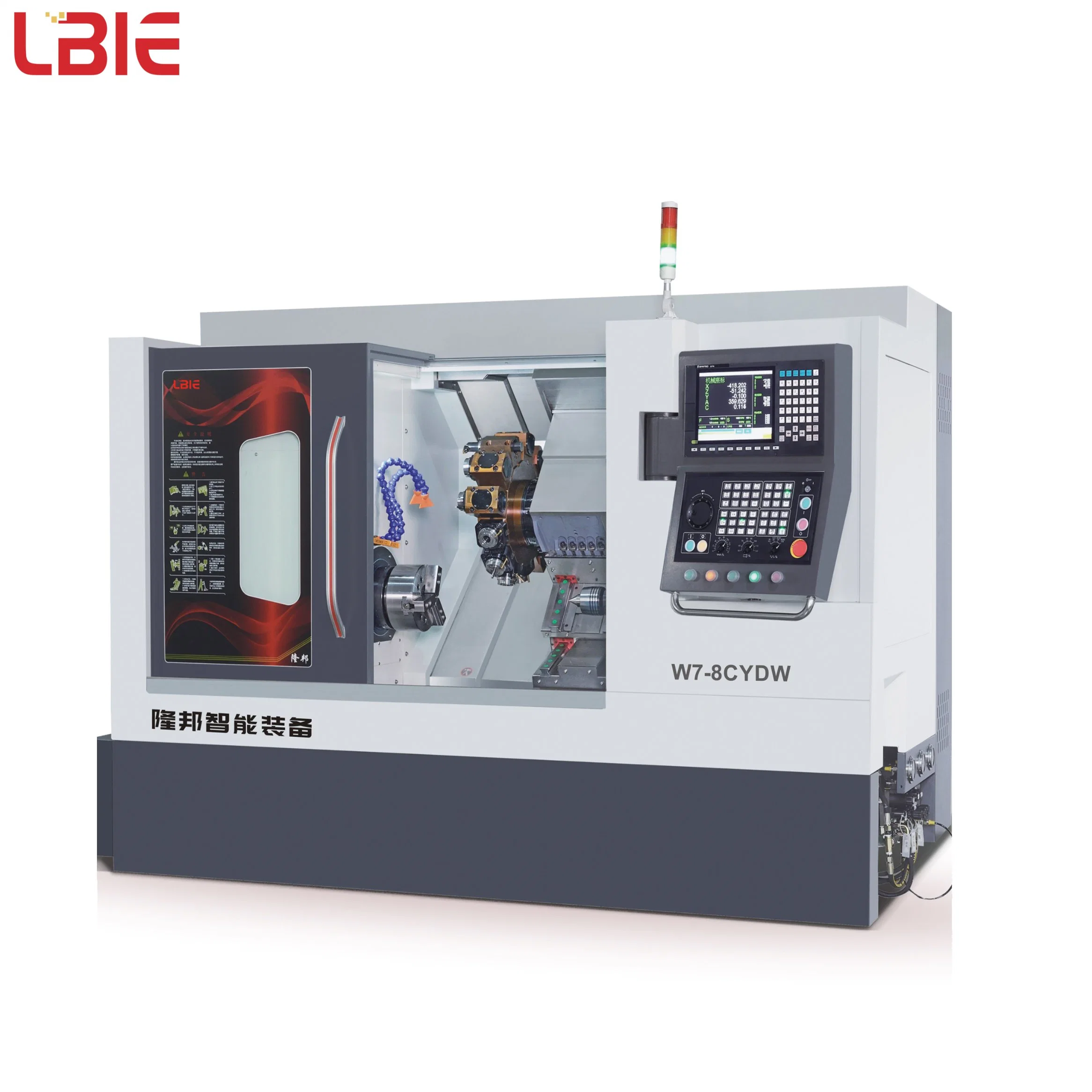
| Item | Unit | Specification | Comment | ||
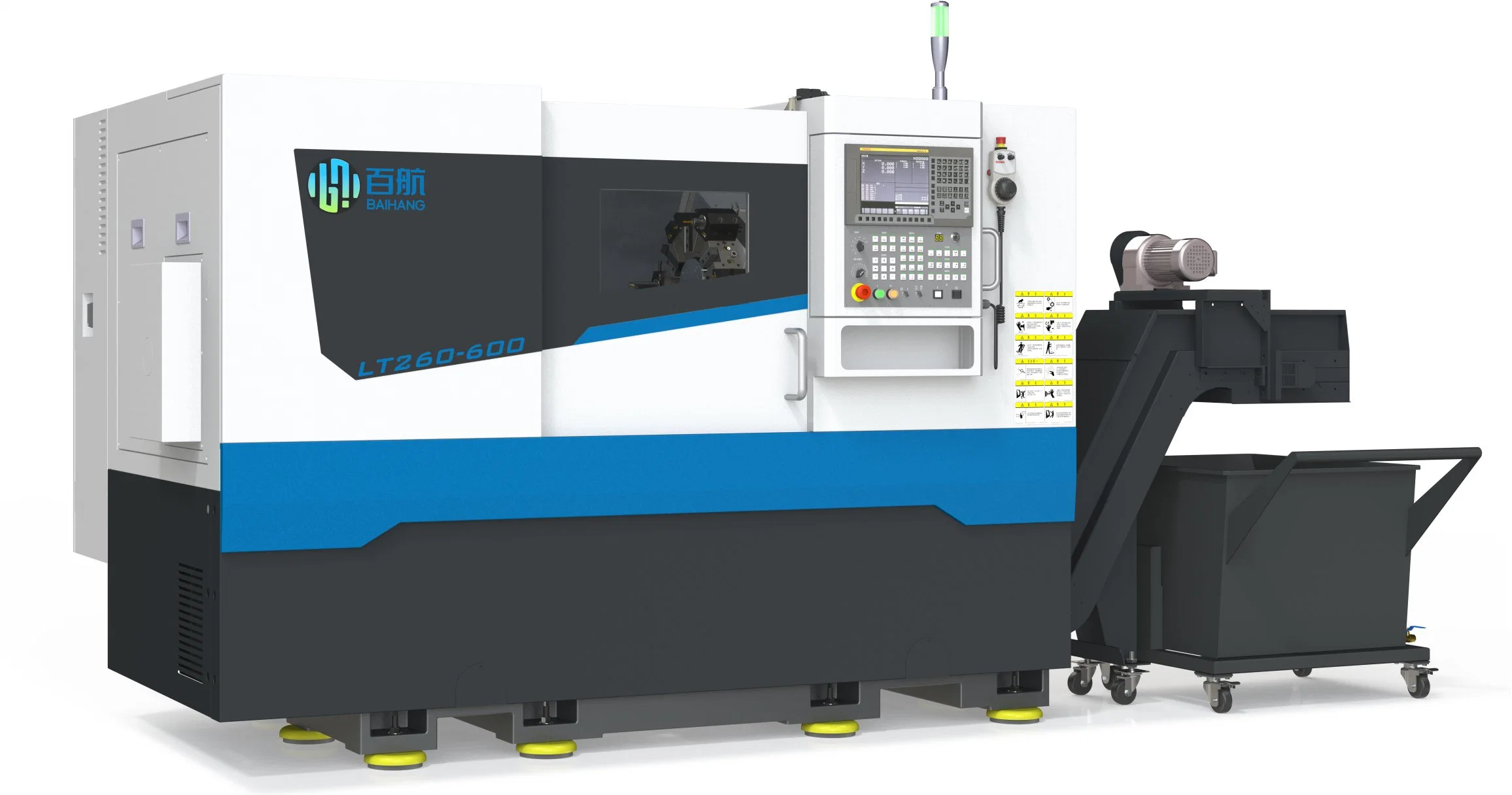
| LT260-600 | |||||
| The maximum rotating diameter on the lathe bed | mm | 520 | |||
| The maximum cutting length | mm | 600 | |||
| The maximum cutting diameter | mm | 360 | |||
| The standard cutting diameter | mm | 210 | |||
| The maximum rotating diameter on the slide | mm | 360 | |||
| Spindle end type and code | A2-6 | ||||
| Spindle hole diameter | mm | 62 | |||
| Processing bar diameter | mm | 50 | |||
| Spindle | Spindle speed range | r/min | 50~4500 | ||
| Spindle continuous output torque | Nm | 130 | FANUC SYSTEM | ||
| 130 | GSK SYSTEM | ||||
| Spindle maximum output torque | Nm | 235 | FANUC SYSTEM | ||
| 177 | GSK SYSTEM | ||||
| Spindle speed series | Stepless speed change | ||||
| Main motor output power | kW | 11/15min(βilp22) | |||
| Chuck | Chuck diameter | inch | 8² | ||
| X-axis rapid traverse speed | m/min | 24 | |||
| Z-axis rapid traverse speed | m/min | 30 | |||
| X-axis itinerary | mm | 200 | |||
| Z-axis itinerary | mm | 645 | |||
| Overall tailstock itinerary | mm | 450 | |||
| Tailstock sleeve itinerary | mm | 100 | |||
| Taper of tailstock sleeve taper hole | Mohs | 5# | |||
| Standard tool holder form | Horizontal servo 12 positions | ||||
| Tool size | Outer circle cutter | mm | 25×25 | ||
| Diameter of boring bar | mm | Ф40/Ф32/Ф25/Ф20 | |||
| Maximum bearing capacity | Disk parts | kg | 200 | Include chuck, etc Machine tool accessories | |
| Axial parts | kg | 500 | |||
| Machine weight | kg | 4350/4900 | |||
| Dimensions(Length*Width*Hight) | mm | 2500*1690*1750 | Chip extractor not included | ||
| Inspection item | Factory standard | |
| Radial runout of spindle shaft diameter | 0.003mm | |
| Processing workpiece roundness | 0.002mm/Ф75mm | |
| Processing workpiece cylindricity | 0.008mm / 150mm | |
| Processing workpiece flatness | 0.008mm/Ф200mm | |
| Processing workpiece surface roughness | Ra0.8μm | |
| Positioning accuracy | X-axis | 0.005mm |
| Z-axis | 0.005mm | |
| Repeat positioning accuracy | X-axis | 0.003mm |
| Z-axis | 0.003mm | |
| No. | Name | Manufacturer | Model and specification | Amount | Comment |
| 1 | Numerical control system | FANUC SYSTEM | FANUC 0i-TF | 1set | ★ |
| GSK SYSTEM | GSK988TD | ||||
| 2 | Main motor | FANUC SYSTEM | βiIP22/8000 | 1 set | ★ |
| GSK SYSTEM | ZJY265A-11AM-B5 | ||||
| 3 | X-axis servo motor | FANUC SYSTEM | βiSc12/3000-B(With belt lock) | 1 set | ★ |
| GSK SYSTEM | 130SJTF-MZ096C(A9II) | ||||
| 4 | Z-axis servo motor | FANUC SYSTEM | βiSc12/3000 | 1 set | ★ |
| GSK SYSTEM | 130SJTF-M096C(A9II) | ||||
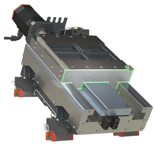
| 5 | X-axis ball screw | Import | φ32×12-635 | 1 set | ★ |
| 6 | Z-axis ball screw | Import | φ32×12-1117 | 1 set | ★ |
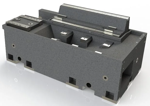
| 7 | X-axis guide | Self-production | Sliding guide | 1 set | ★ |
| 8 | Z-axis guide | Import | 35 specifications | 1 set | ★ |
| 9 | Tailstock guide | Self-production | Sliding guide | 1 set | ★ |
| 10 | Main shaft bearing | Import | 100 in the front, 90 in the back | 1 set | ★ |
| 11 | Lead screw bearing | Import | 25X62X15 | 1 set | ★ |
| 12 | Turret | Import | Horizontal 12 station servo | 1 set | ★ |
| 13 | Chuck cylinder | Import | 8″hollow | 1 set | ★ |
| 8″intersolid | |||||
| 10″intersolid / hollow | |||||
| 14 | Tailstock | Self-production | Hydraulic belt locks | 1 set | ★ |
| 15 | Hydraulic station | Import | pressure 6Mpa, Flow rate 24L/min | 1 set | ★ |
| 16 | Cooling pump | Import | Pumping head 35m,Flow rate 30L/min | 1 set | ★ |
| 17 | Chip removal | Made in China | Postposition chip removal | 1 set | ★ |
| Made in China | Side chip removal | 1 set | |||
| Made in China | Chip box | 1 set |
| No. | Name | Manufacturer | Model and specification | Amount | Comment |
| 1 | Floor mat iron | Made in China | 1 set | ||
| 2 | Turning tool holder | Import | Boring tool clampφ40 | 3 | 12 Station cutter tower |
| End tool holder 25X25 | 1 | ||||
| Round knife press knife block 25X25 | 6 set |
| No. | Name | Amount | Comment |
| 1 | Safety instruction | 1 | Electronic edition |
| 2 | Maintenance manual | 1 | Electronic edition |
| 3 | Transport and installation instructions | 1 | Electronic edition |
| 4 | Operating instruction | 1 | Electronic edition |
| 5 | Certificate of conformity | 1 | |
| 6 | Packing list | 1 | |
| 7 | Chuck,cylinder operation manual (or maintenance manual) | 1 for each | |
| 8 | Lubrication pump specification | 1 | Electronic edition |
| 9 | Turret instruction manual | 1 | Electronic edition |
| 10 | Hydraulic system operating instructions | 1 | Electronic edition |
| 11 | Machine tool instruction Manual (Electrical) | 1 | Electronic edition |
| 12 | Programming and operation manual | 1 | Electronic edition |
| 13 | Driver unit user manual | 1 | Electronic edition |
| 14 | Circuit book | 1 | Electronic edition |