Description
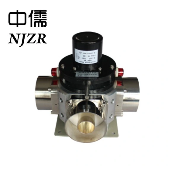
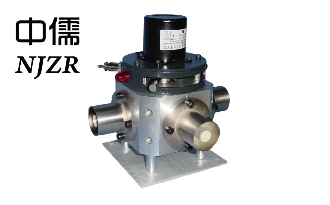
1/3/5/10KW antenna coaxial switch technical document
1. Shell material: Anti oxidation treated aluminum alloy;
2. The reed adopts imported "beryllium bronze" belt and adopts silver plating process;
3. The contact points of the spring are formed in one mold, forming a circular arc shape with multiple contact points at each joint;
4. The motor adopts a permanent magnet motor with low speed and synchronous function;
5. The motor power supply is AC 220V, frequency 50Hz, and current 0.5A
6. Output electric control contact mode (excluding motor control): each position
There is one set of normally open contacts
7. Position status indication: There is an indicator light in place on the coaxial switch; Indicator panel.
8. Withstand power: greater than rated power;
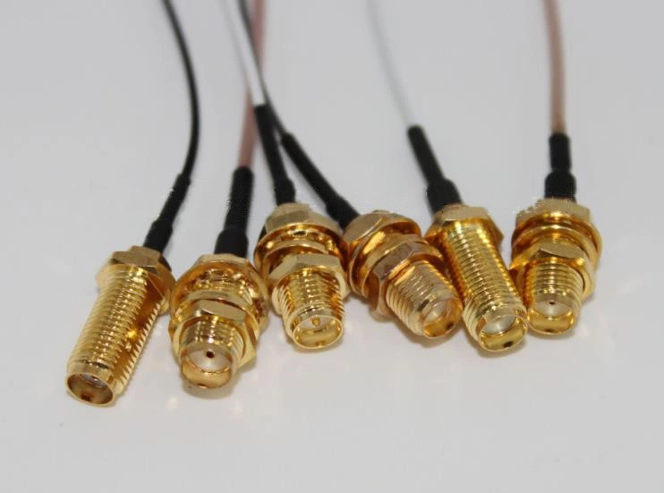
9. Interface form: 4-1/2 straight pipe φ 80 straight pipes φ 40 straight pipes, L27;
10. Equipped with remote control and telemetry module for PC remote control
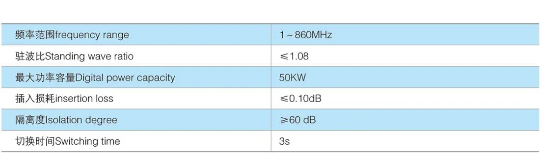
Coaxial switch performance
1. Rotation mode: manual and electric integration, automatic control;
2. Frequency: DC~860MHz
3. Insertion loss less than 0.08dB;
4. Isolation degree ≥ 60dB;
5. Standing wave ratio: ≤ 1.1;
6. Switching time:<3 seconds;
7. Weight: according to different specifications of the actual product
Coaxial switches have a wide range of applications in RF/microwave systems, such as time multiplexers, time division channel selection, pulse modulation, transceiver switches, beam adjustment, etc. The indicators of the switch are relatively simple, with minimal on loss and maximum off loss. The frequency band and power meet the system requirements.
The components that make up the coaxial switch include ferrite, PIN tube, FET or BJT. Ferrite and PIN are classic switching devices. Table 1 shows the performance comparison of the two devices. Ferrite is characterized by high power and low loss, while PIN is characterized by fast speed and low cost. FET or BJT has gain and has become the main device for medium and small power switches. Coaxial switches for various devices have their own usage scenarios.
The principle of a ferrite switch is to change the direction of the bias magnetic field, achieve a change in permeability, and change the transmission constant of the signal to achieve the switching purpose.
The PIN tube has a switching effect on microwave signals under the action of forward and reverse low-frequency signals. The attenuation of the microwave signal is very small (0.5dB) during forward bias, and significant (25dB) during reverse bias.
Performance indicators| | 300W antenna coaxial switch | 1KW antenna coaxial switch | 3/5KW antenna coaxial switch | 10 KW antenna coaxial switch |
| Output interface | L16 | 1 5/8, φ40 | 1 5/8, φ40 | 3 1/8, φ80 |
Insertion loss (db)
Return loss (db)
Isolation degree (db) | 0.1
≥28
≥50 | 0.1
≥28
≥50 | 0.1
≥28
≥50 | 0.1
≥28
≥50 |
| Impedance(Ω) | 50 | 50 | 50 | 50 |
| Switching time (seconds) | 2 | 2 | 2 | 2 |
| driving voltage | 220VAC-50Hz | 220VAC-50Hz | 220VAC-50Hz | 220VAC-50Hz |
Current (A) | 0.5 (starting)
0.25 (running) | 0.5 (starting)
0.25 (running) | 0.5 (starting)
0.25 (running) | 0.5 (starting)
0.25 (running) |
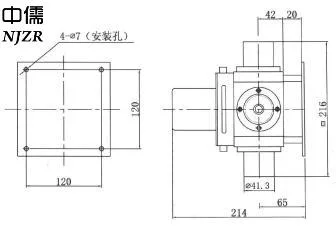
Outline dimension drawing


 Complaint