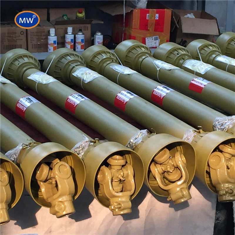
The Drive Shaft Joint For Class Baler is a key component of the Class B baler. It provides constant rotary speed to the power take off shaft of about 1,000 revolutions per minute. It is also important to know the function of the Flywheel and the Angle adjustment mechanism. After reading this article, you will be able to choose the right Drive Shaft Joint for your Class B baler.
If you have questions or need further information, feel free to contact us.
Angle adjustment mechanism
The angle adjustment mechanism for drive shaft joint of a class baler is a common component of this machine. It is associated with the feed mechanism 15 and the knotter drive. In addition, the feed mechanism is pivotally supported on the knotter shaft by brackets. The rotatable drive shaft 64 is supported by bearing sleeves 62, which are also arranged on the frame. The axis of rotation is parallel to the pivot pin, which allows for accurate correction of the angle.
The angle adjustment mechanism for drive shaft joint of a class baler is a pivoting system that adjusts the ram's angle relative to the main gear. The angle adjustment mechanism is connected to the knotter shaft and pivots to adjust the needle bar's position.
It also allows the baler to change the pitch of the needle bar 23, thereby adjusting the pitch of the baler.
Power transmission device
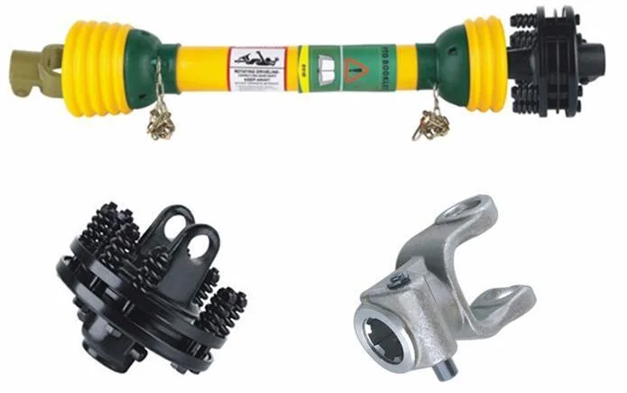
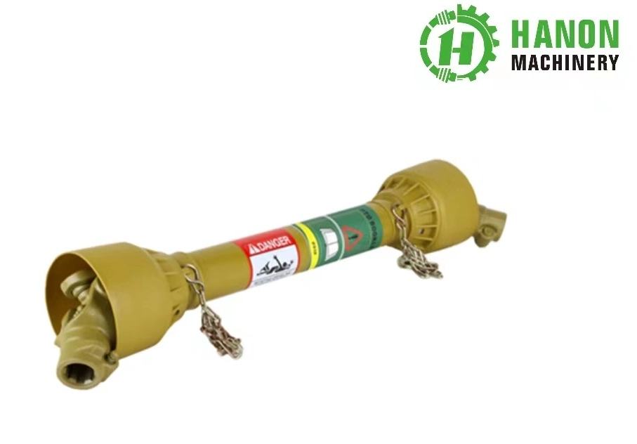
A power transmission device for a class baler includes a refraction unit coupled to the rear panel of the tractor and configured to connect the input drive shaft of the baler with the tractor's power take-off sleeve. The refraction unit includes a universal joint and two cover parts disposed on the left and right sides. The drive shaft of the baler is then connected to the articulation joint.
The power take-off shaft of the tractor 3 and the input drive shaft of the class baler are coupled together with the articulation joint. A second protective part is installed on the rear surface of the refraction part to surround the connection portion between the input driving shaft and output shaft of the universal joint. This part also provides the baler with a place to reposition itself in case of any malfunction or failure.
Twine tube speed control
The present invention provides for the efficient speed control of twine tubes 30 and 32 in a class baler. The tubes are positioned equally and parallel to the bale's longitudinal axis. The movement of the twine tubes is not linear; rather, it increases as the twine tube ends move. The present invention also provides for the automatic speed control of twine tubes 30 and 32.The hydraulic fl ow control valve is used to regulate the speed of the twine tube. When it reaches the left side of the bale, the lever reverses and releases the twine tube. The twine is then cut on a knife. The speed control valve can be adjusted to slow the twine's travel but is not always possible to do so. Therefore, the speed control of the twine tube is important for safe operation.
Flywheel
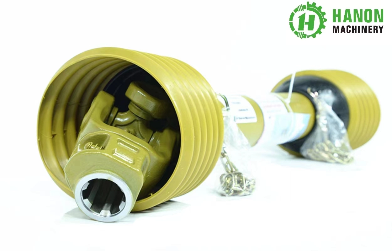
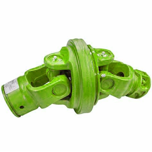
A class baler's drive shaft comprises a flywheel, or the rotating member, which is encased within a chamber 58. A universal joint is welded to the shaft at the knuckle part 35, which in turn rotates the flywheel. The knuckle part and a washer-like ring are connected by the shaft to a drive sleeve.
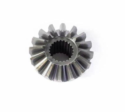
A flywheel 8 is arranged in the front portion of the baling channel and is connected to the main drive shaft 7 by a flywheel drive shaft. The main drive shaft also includes a cross-shaft 10 which projects from opposite sides of the main drive housing. This shaft carries an operating crank 11 on each end. In addition, a power take-off gear 12 engages the operational elements of the class baler.
The flywheel drive shaft joint of a class baler includes a slip clutch and friction clutch. The friction clutch is able to deliver
substantially constant driving speeds based on the flywheel's inertia. In some cases, the flywheel is coupled to a cushioning element for added comfort. Further, the drive shaft is angled to the shaft, which means it cannot be positioned directly on the drive shaft.


 Complaint