 Complaint

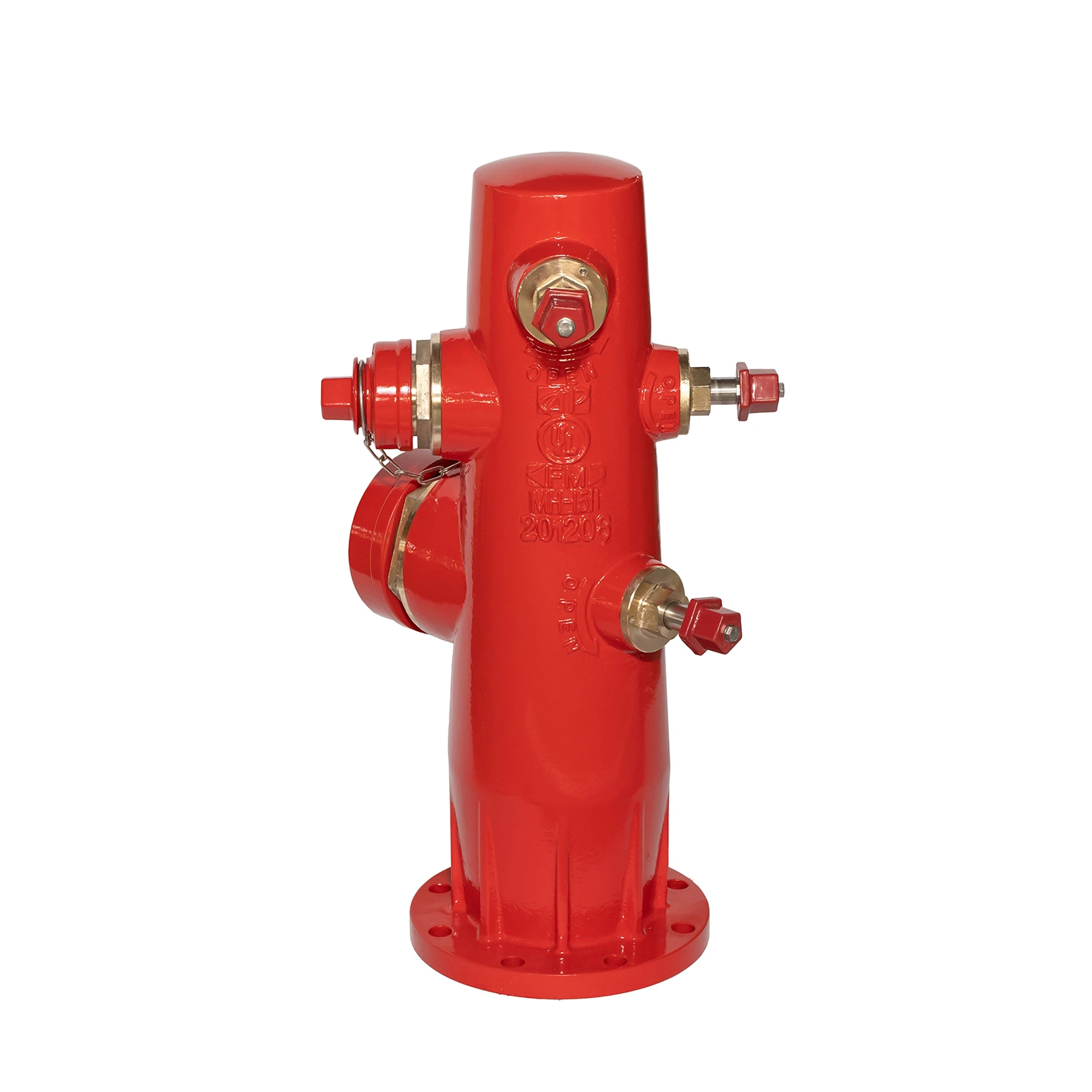
| 40 | Bolt | 2 | SS304 | ASTM A240 |
| 39 | Screw stem bushing | 1 | SS304 | ASTM A240 |
| 38 | 100 Cover gasket | 1 | EPDM | ASTM D2000,EPDM |
| 37 | 100 Connector | 1 | C95400 | ASTM B148 |
| 36 | Check turn gasket | 1 | Gr.B | ASTM A283-B |
| 35 | Locking nut gasket | 1 | DI | ASTM A536 Grade 65-45-12 |
| 34 | Platen | 1 | DI | ASTM A536 Grade 65-45-12 |
| 33 | Annular tubes | 1 | 1045 | ASTM A29\29M |
| 32 | Bolt,Nut | 6 | 1035 | ASTM A29\29M |
| 31 | Seat fixing plate | 1 | DI | ASTM A536 Grade 65-45-12 |
| 30 | Bolt,Nut | 2 | SS304 | ASTM A240 |
| 29 | Seat | 1 | C95400 | ASTM B148 |
| 28 | Drain hole cover | 1 | C95400+EPDM | ASTM B148+ASTM D2000,EPDM |
| 27 | Cushipn rubber | 1 | EPDM | ASTM D2000,EPDM |
| 26 | Screw stem | 1 | 1045 | ASTM A29\29M |
| 25 | Bolt,Nut | 8 | 1035 | ASTM A29\29M |
| 24 | Cover chain | 3 | Gr.B | ASTM A283-B |
| 23 | Cylindrical pin | 1 | 1045 | ASTM A29\29M |
| 22 | 100 cover | 1 | DI | ASTM A536 Grade 65-45-12 |
| 21 | Bolt,Nut | 8 | 1035 | ASTM A29\29M |
| 20 | Screw nut seat | 1 | C95400 | ASTM B148 |
| 19 | Screw nut gasket | 1 | C95400 | ASTM B148 |
| 18 | Screw stem nut | 1 | C95400 | ASTM B148 |
| 17 | Thread plug | 1 | C95400 | ASTM B148 |
| 16 | Upper end cover | 1 | DI | ASTM A536 Grade 65-45-12 |
| 15 | 65 Cover | 2 | DI | ASTM A536 Grade 65-45-12 |
| 14 | 65 Cover gasket | 2 | EPDM | ASTM D2000,EPDM |
| 13 | 65 Connector | 2 | C95400 | ASTM B148 |
| 12 | Main body on ground | 1 | DI | ASTM A536 Grade 65-45-12 |
| 11 | Clamp for connection tube | 1 | DI | ASTM A536 Grade 65-45-12 |
| 10 | Connecting rod sleeve | 1 | 1045 | ASTM A29\29M |
| 09 | Perforated cylindrical pin | 2 | 1045 | ASTM A29\29M |
| 08 | Connecting cylinder | 1 | DI | ASTM A536 Grade 65-45-12 |
| 07 | Drain hole spring | 2 | SS316 | ASTM A240 |
| 06 | Sealed rubber sheet | 1 | EPDM | ASTM D2000,EPDM |
| 05 | Tray | 1 | DI | ASTM A536 Grade 65-45-12 |
| 04 | Locking nut gasket | 1 | EPDM | ASTM D2000,EPDM |
| 03 | Connecting rod | 1 | 1045 | ASTM A29\29M |
| 02 | Locking nut gasket | 1 | DI | ASTM A536 Grade 65-45-12 |
| 01 | Flange connector or Mechnical connector | 1 | DI | ASTM A536 Grade 65-45-12 |
| Part No. | Part Name | Qty.Req'd | Material | Specification |
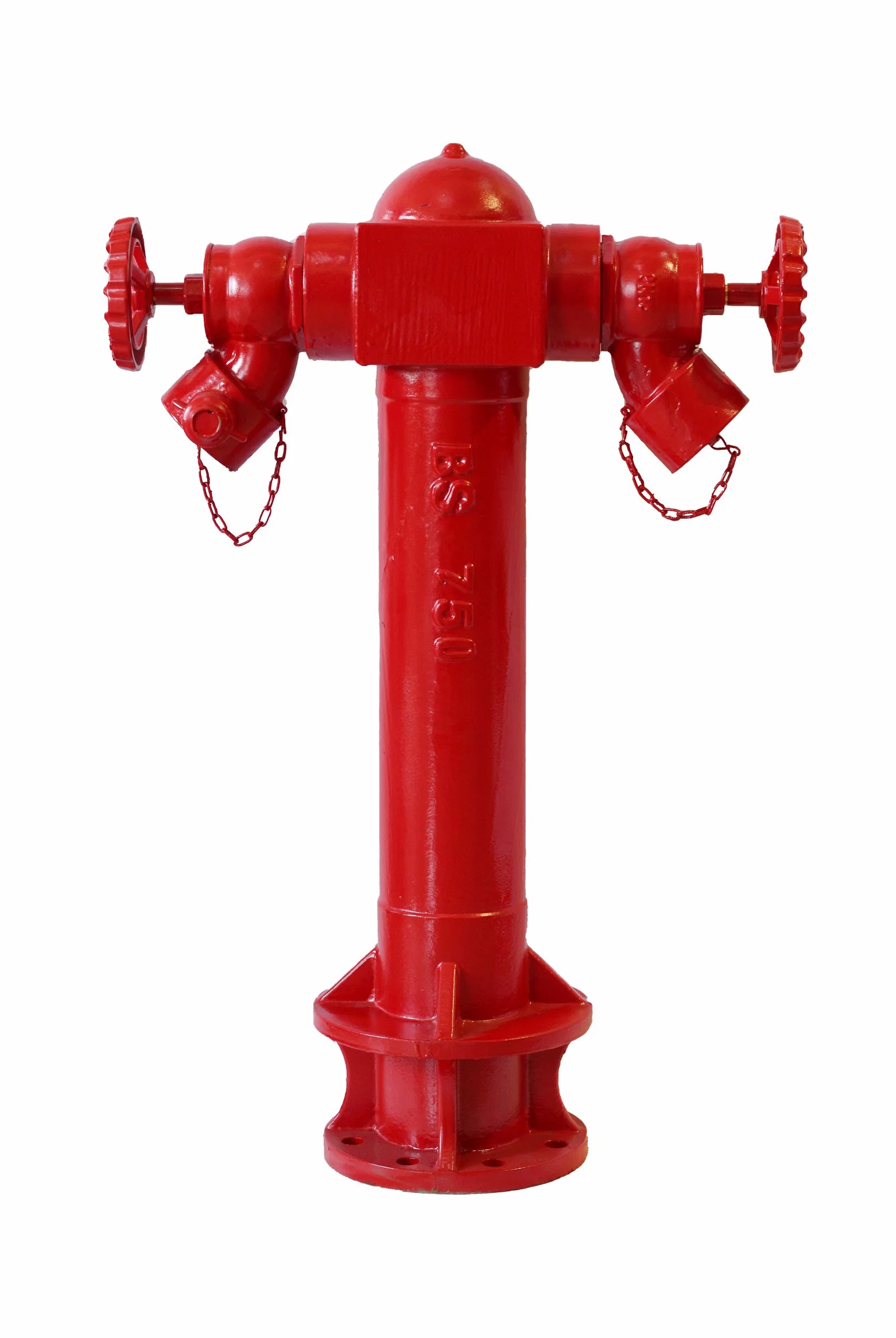
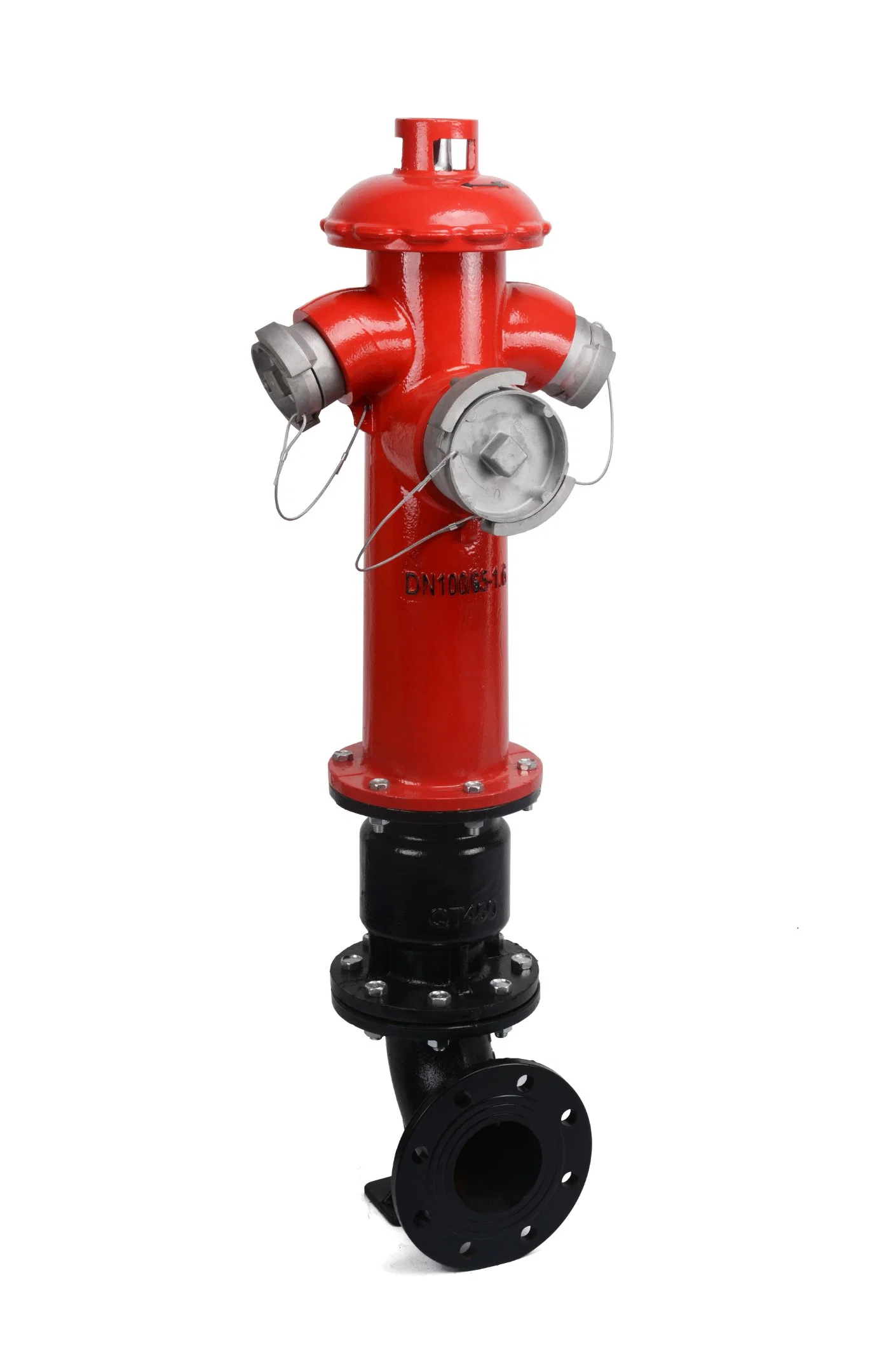
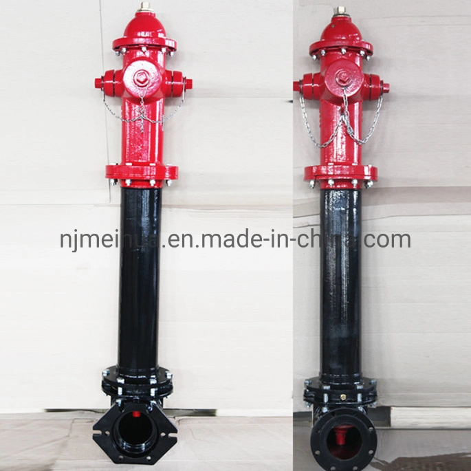
| Model Number | Dimension mm(mm/inch) | Weight(kg) | |||
| A(mm/inch) | B(mm/inch) | C(mm/inch) | D(mm/inch/feet) | ||
| MH-1510FA MH-1510A | 208/8.2 | 805/31.7 | 460/18.1 | 911/36/3 | 178 |
| 1063/42/3'6" | 185 | ||||
| 1215/48/4' | 190 | ||||
| 1368/54/4'6" | 196 | ||||
| 1520/60/5' | 211 | ||||
| 1673/66/5'6" | 220 | ||||
| 1825/72/6' | 241 | ||||
| 1978/78/6'6" | 246 | ||||
| 2130/84/7' | 251 | ||||