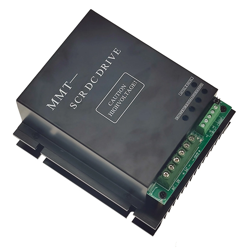
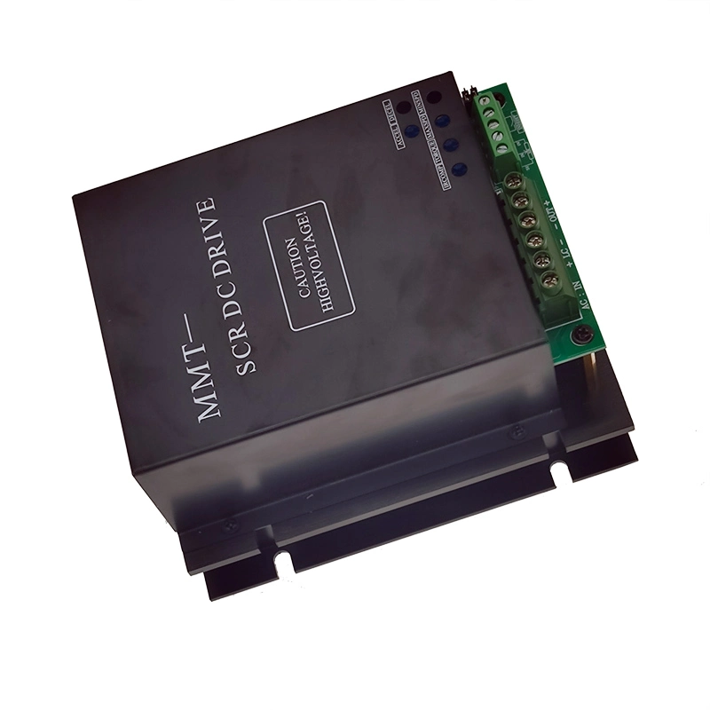
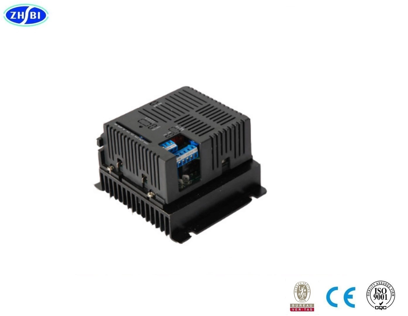
Please contact the staff for details of the DC brush motor governor instruction manual
Characteristics of products
1. PWM pulse width modulation technology, low noise
2. Speed regulation ratio 1:100 (open-loop)
3. The starting torque at low speed is big
4. Double closed loops PI regulation
5. Current settings, current limiting protection, over-current warning, output stop.
6. Setting function of soft starting. (0.3-10 seconds adjustable)
7. Torque compensation adjustment
8. The maximum output limit function
9. Short-circuit protection
10. Self-inspection alarm output function
11. Standard signal interface (After fitting signal isolator, the device can adapt to various D \
A signal, 0-5 V or 0-10 V or 4-20 mA)
12. With fast response and good following.
13. Function of enabling block control
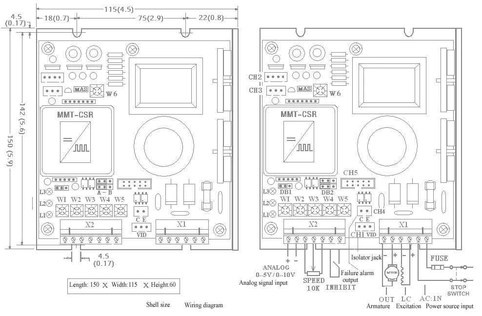
. . The main technical parameters
1. The input voltage: AC 110V/220V ± 10%
2. The output voltage: DC 0 ~ 110V/220V or other voltage can be set
3. Rated output current: DC 6A 8A 10A
4. Rated excitation voltage / current: DC 220V(110)/3A
5. The output voltage accuracy: ≤1%
6. The environment temperature: -10 º C to +60 º C
7. The environment Humidity: ≤1% 80 RH relative humidity. (Non-condensing)
. Product performance
1. The mechanical characteristics of hardness, static error rate of 1%.
2. A wide speed-regulating range (0 - max).
3. A rapid dynamic response process.
4. Automatic and smooth transition process during acceleration or deceleration.
5. Better excavator characteristics, can limit overload current to set value current. 6. High reliability and compact structure, high performance-price ratio.
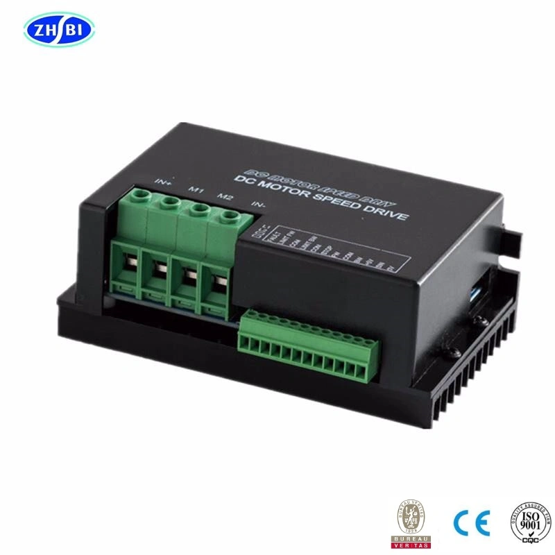
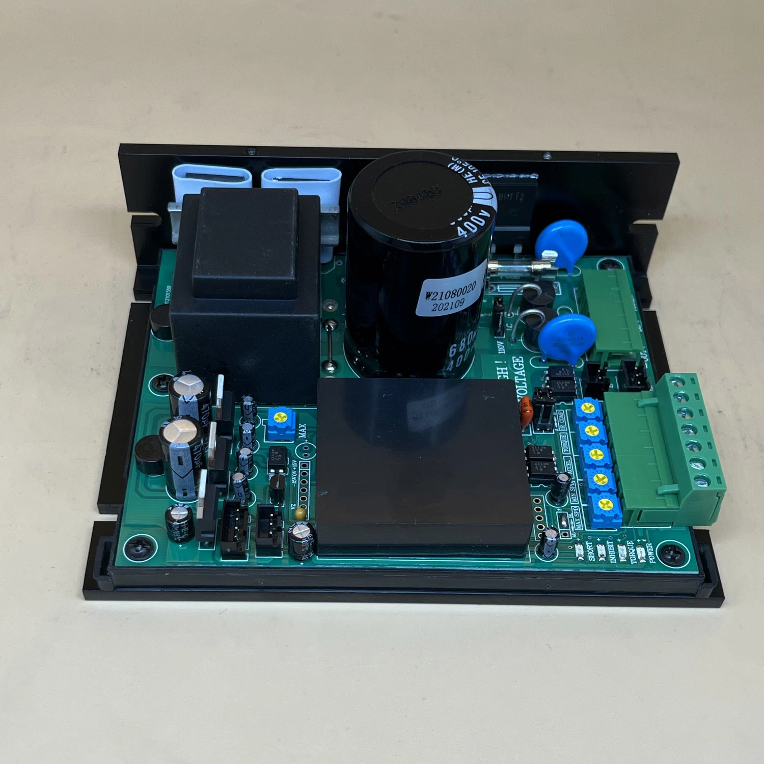
. Instructions on adjustment of potentiometer
1. The maximum rotation speed setting adjustment MAX SPD (see figure W1)
With this potentiometer, the greatest output voltage of driver can be confirmed (the
maximum motor rotation speed)
Clockwise adjustment -----------to raise output voltage
Counterclockwise adjustment ----- to reduce the output voltage
Note: when it is not sure that the maximum output voltage of driver matches with the rated
voltage of motor, "MAX SPD" potentiometer should be adjusted to the minimum (the
largest anti-clockwise), then the external speed potentiometer should be adjusted to the
largest, and then "MAX SPD" potentiometer will be regulated again until the output
voltage of driver and rated voltage of motor matches (that is, the motor's rated rotation
speed)
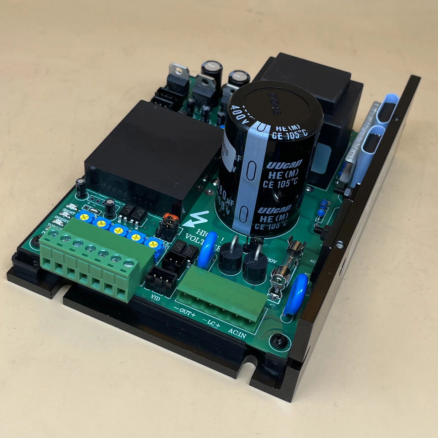
2. The lowest rotation speed setting adjustments: (Supplementary to the given signal) MIN
SPD (see figure W2)
Adjust speed of potentiometer to the minimum, then adjust MIN SPD potentiometer, so
you can determine the slowest rotation speed of motor.
Clockwise adjustment ----------- to increase the auxiliary given signal
Anti-clockwise adjustment ----- to reduce the auxiliary given signal
Note: External signal is set as 0, if there are still certain requirements of motor's speed, it
can be realized by adjustment of potentiometer (adjustment range 0 --- 30%) At this time, if
given external given signal is increased, the rotation speed of motor will increase on the
basis of "MIN SPD" setting value. 3. Soft-start time adjustment: ACCEL (see figure W3)
This adjustment of potentiometers ACCEL can make sure motor's rising slope from the
initial velocity up to the highest velocity (that is rising time, set time adjustable during 0-10
seconds). See figure 1
Clockwise adjustment -----------to increase soft-start time
Anti-clockwise adjustment ------ to reduce soft-start time
 Complaint