Description
43dBm Wireless Coupling Tetra VHF UHF Fiber Optic Repeater
Our tetra repeates have CE 0865 certificate with report,freely to import to European!
This repeater is mainly applicable to such case:
Underground fiber optic cable network already exists beneath the area to be covered;there is huge obstructive terrain between the BTS and the area to be covered;the distance between the BTS and the area to be covered is 20 km around.
IntroductionThe Fiber Optic Repeater system consists of two parts: Donor Unit and Remote Unit.One Master can work together with 1 to 8 Slaves. The Master transfers the BTS signal into optical signal and transmits the optical signal to the Slaves. The Slaves transfer the optical signal into RF signal, amplify the RF signal and cover the target areas. The application of Fiber Optical repeaters will effectively eliminate the signal blind areas, enhance the network quality, improve the image of cellular operators and bring them more profit.Technical features1.Aluminum alloy enclosure for excellent heat dissipation,waterproof design for all-weather installation;2.Adopting filter with highly selectivity and low insertion loss eliminates interference between uplink and downlink;3.Modules structure,full-duplex & dual-port design, and built-in power supply,easy for maintenance and installation;4.High linearity PA; high system gain;5.ALC and AGC to ensure stable operation;6.Max transmission distance between Donor Unit and Remote Unit is 20KM;7.Local PC GUI operation and Optional Remote Modem control.8.Can support up to 24 pcs RU with 1 pcs MUTypical applications
wireless coupling Fiber Optic Repeater for-application
Main Specification
Master Unit for wireless coupling | Main Item | Specification(on user requirement) |
| UpLink | DownLink |
| Frequency Range | CDMA850 | 824 ~ 849 MHz | 869~ 894MHz |
| GSM&EGSM | 880 ~ 915 MHz | 925 ~ 960 MHz |
| DCS1800 | 1710 ~ 1785 MHz | 1805 ~ 1880 MHz |
| PCS1900 | 1850 ~ 1910 MHz | 1930~ 1990 MHz |
| WCDMA2100 | 1920 ~ 1980 MHz | 2110 ~ 2170 MHz |
| AWS2100 | 1710 ~ 17555 MHz | 2110 ~ 2155 MHz |
| IDEN | 806 ~ 821Mhz | 851 ~ 866 Mhz |
| TETRA | 350 ~520 Mhz | 350 ~520 Mhz |
| Customized frequency | Customized frequency |
| LTE | 700MHZ(A,B,C,D band optional |
| 2500 ~ 2570 MHz | 2620 ~ 2690 MHz |
| Customized frequency | Customized frequency |
| Bandwidth | 5MHz (Cavity Filter) |
| Carrier channel number | Up to 8 |
| Maximum Gain | 45dB±2dB | 55dB±2dB |
| ALC | Input power increase 20dB,output power keep within the maximum output power +2dB |
| Frequency Error | ≤±0.5ppm |
| Gain Control Range | 0~30dB |
| RF Output Power | 37dBm | 10dBm |
| Noise Figure | ≤5dB |
| Group Delay | ≤5us |
| Inband Flatness | ≤3dB(P-P)/ Within Effective working band ;≤2dB(P-P)/Within channel |
| Intermodulation attenuation | Inband | ≤-50dBc/30KHz |
| Outband (0ff 2.5MHz) | ≤-36dBm/30KHz@9KHz-1GHz |
| ≤-30dBm/[email protected] |
| Outband Rejection | Selective Channel | ≤-30dBc/30kHz@±200kHz |
| ≤-60dBc/30kHz@±400kHz |
| BroadBand | ≤-40dB@2.5MHz |
| ≤-60dB@10MHz |
| Selective Band | ≤-30dBc/30kHz@±400kHz |
| ≤-60dBc/30kHz@±600kHz |
| Spurious emission | ≤-36dBm/30KHz@9KHz-1GHz |
| ≤-30dBm/[email protected] |
| VSWR | ≤1.5 |
| Power Supply | 220VAC,110VAC,48VDC,24VDC |
| Size | 530mm x320mm x200mm/610mmx440mmx250mm |
| Weight | 28Kg/35kg |
| working temperature | -30ºC~+65ºC |
| Relative humidity | ≤95% |
| Monitoring function | RJ45,SMS |
| Others | Refer to user manual for more specification |
| Fiber Connector | FC/APC or SC/APC |
| Fiber Mode | Single mode |
| Optic Wavelength | 1310nm or 1550nm |
| Optic Output Power | -9dBm~-3dBm Optical output power tolerance power rating ±1dB |
| Maximum allowable optical loss | ≥20dB |
Slave Unit RU| Main Item | Specification(on user requirement) |
| UpLink | DownLink |
| Frequency Range | CDMA850 | 824 ~ 849 MHz | 869~ 894MHz |
| GSM&EGSM | 880 ~ 915 MHz | 925 ~ 960 MHz |
| DCS1800 | 1710 ~ 1785 MHz | 1805 ~ 1880 MHz |
| PCS1900 | 1850 ~ 1910 MHz | 1930~ 1990 MHz |
| WCDMA2100 | 1920 ~ 1980 MHz | 2110 ~ 2170 MHz |
| AWS2100 | 1710 ~ 17555 MHz | 2110 ~ 2155 MHz |
| IDEN | 806 ~ 821Mhz | 851 ~ 866 Mhz |
| TETRA | 350 ~520 Mhz | 350 ~520 Mhz |
| Customized frequency | Customized frequency |
| LTE | 700MHZ(A,B,C,D band optional |
| 2500 ~ 2570 MHz | 2620 ~ 2690 MHz |
| Customized frequency |
| Bandwidth | 5MHz (Cavity Filter) |
| Carrier channel number | Up to 8 | |
| Maximum Gain | 55dB±2dB | 45dB±2dB |
| ALC | Input power increase 20dB,output power keep within the maximum output power +2dB |
| Frequency Error | ≤±0.5ppm |
| Gain Control Range | 0~30dB |
| RF Output Power | 10dBm | 43dBm |
| Noise Figure | ≤5dB |
| Group Delay | ≤5us |
| Inband Flatness | ≤3dB(P-P)/ Within Effective working band ;≤2dB(P-P)/Within channel |
| Intermodulation attenuation | Inband | ≤-50dBc/30KHz |
| Outband (0ff 2.5MHz) | ≤-36dBm/30KHz@9KHz-1GHz |
| ≤-30dBm/[email protected] |
| Outband Rejection | Selective Channel | ≤-30dBc/30kHz@±200kHz |
| ≤-60dBc/30kHz@±400kHz |
| BroadBand | ≤-40dB@2.5MHz |
| ≤-60dB@10MHz |
| Selective Band | ≤-30dBc/30kHz@±400kHz |
| ≤-60dBc/30kHz@±600kHz |
| Spurious emission | ≤-36dBm/30KHz@9KHz-1GHz |
| ≤-30dBm/[email protected] |
| VSWR | ≤1.5 |
| Power Supply | 220VAC,110VAC,48VDC,24VDC |
| Size | 530mm x320mm x200mm/610mmx440mmx250mm |
| Weight | 28Kg/35kg |
| Relative humidity | ≤95% |
| Monitoring function | RJ45,SMS |
| Others | Refer to user manual for more specification |
| Fiber Connector | FC/APC or SC/APC |
| Fiber Mode | Single mode |
| Optic Wavelength | 1310nm or 1550nm |
| Optic Output Power | -9dBm~-3dBm Optical output power tolerance power rating ±1dB |
| Maximum allowable optical loss | ≥20dB |
3. Structure Diagram
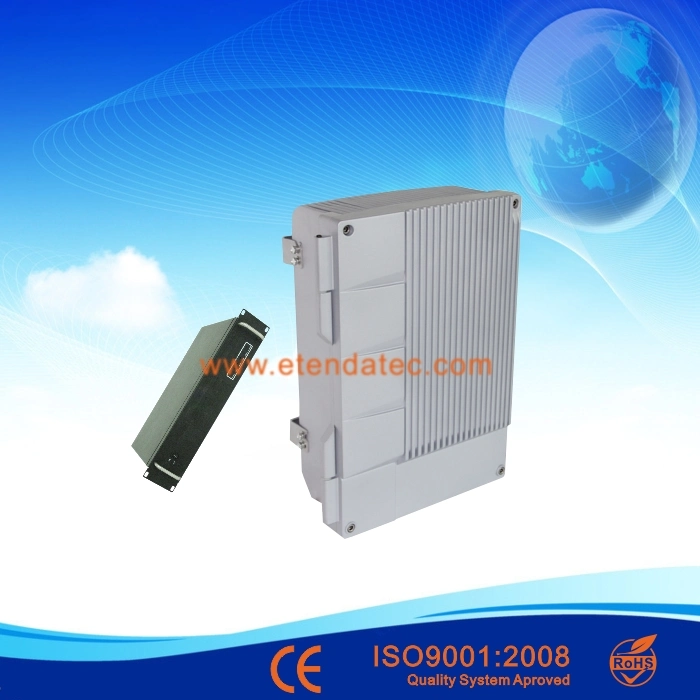
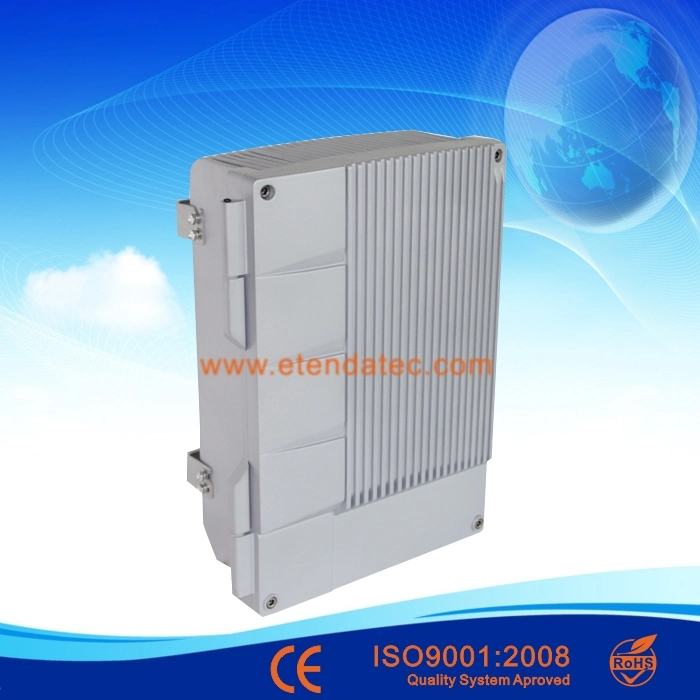
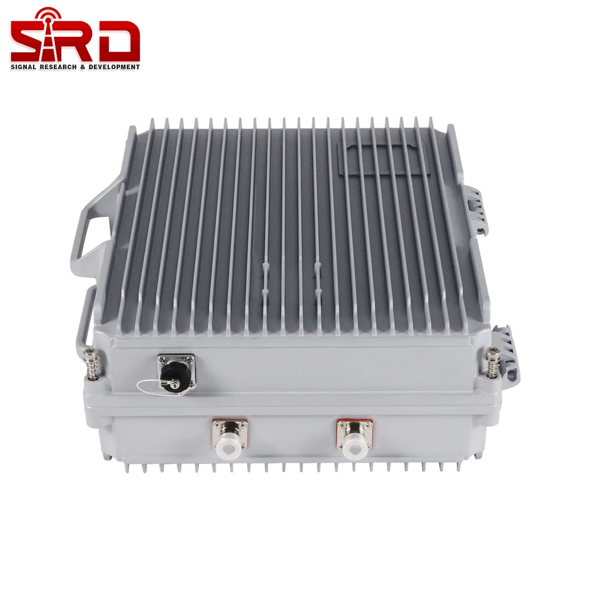
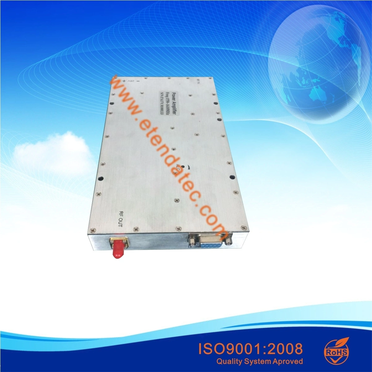
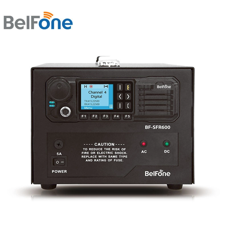
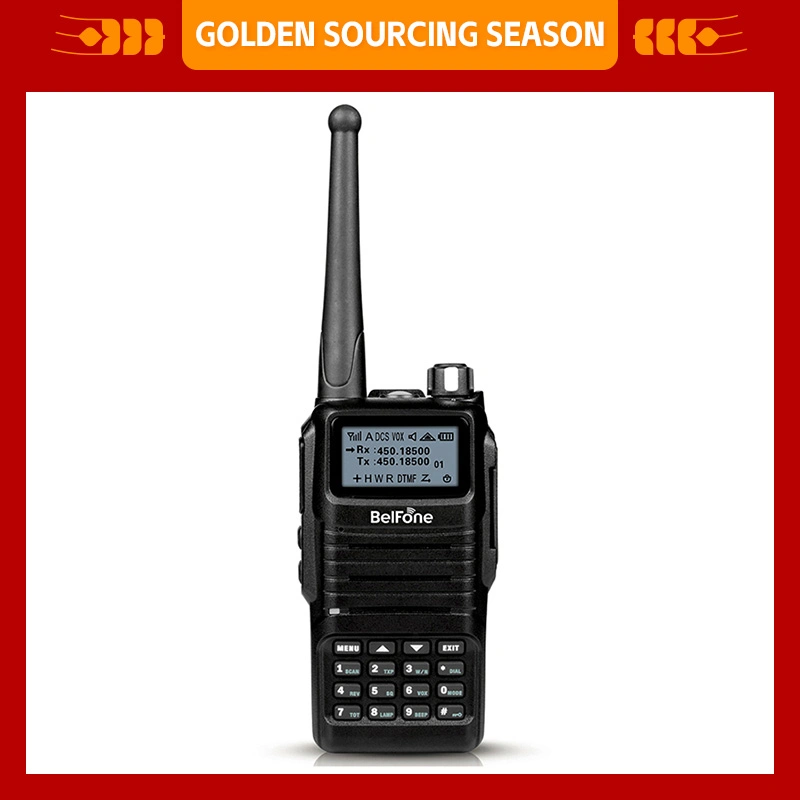
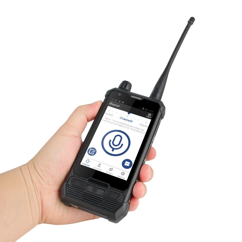
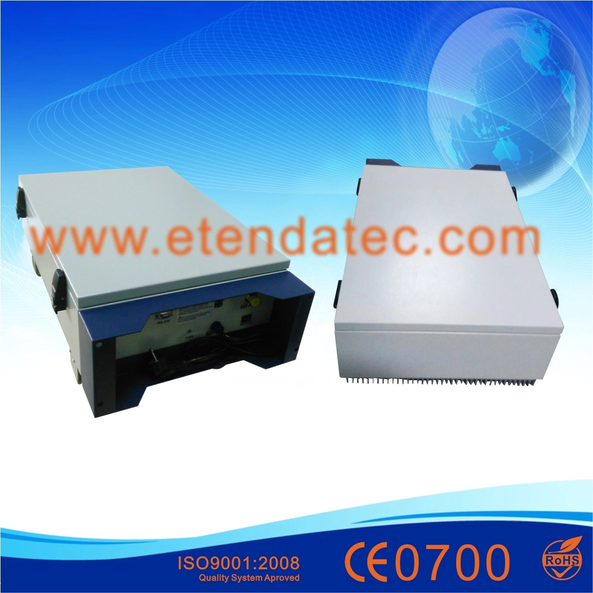
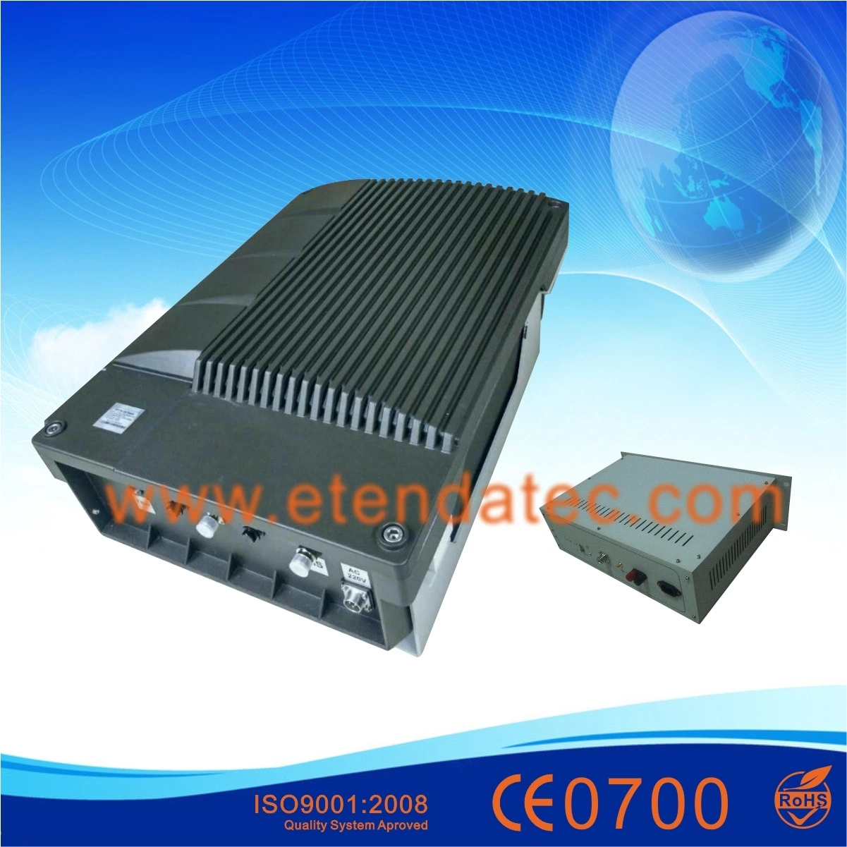
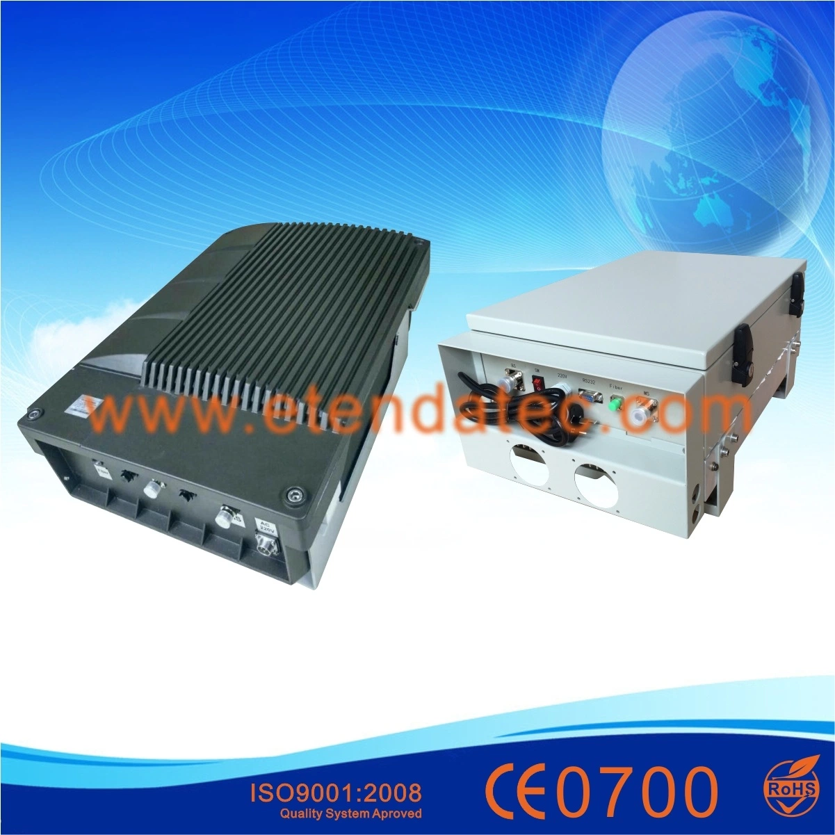
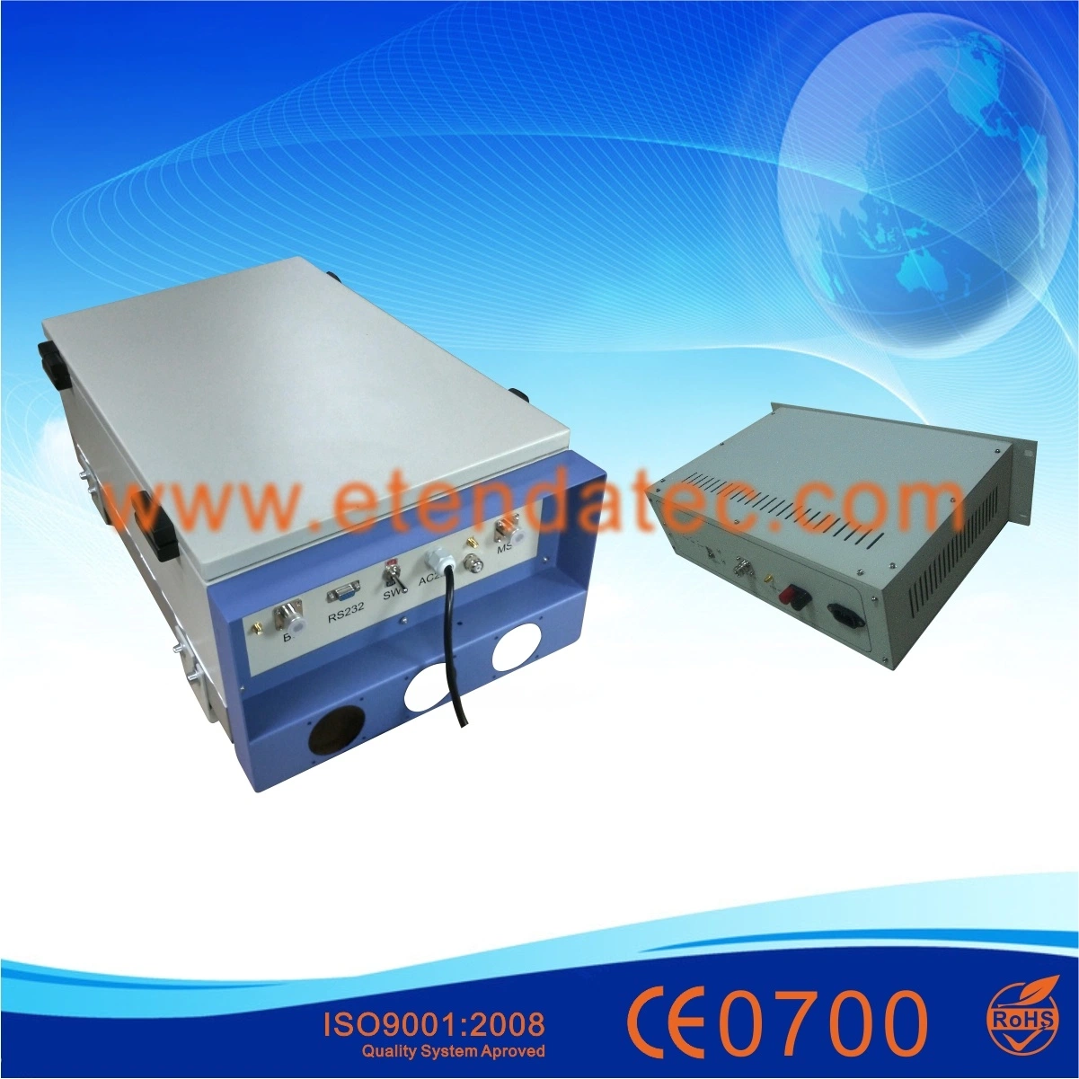
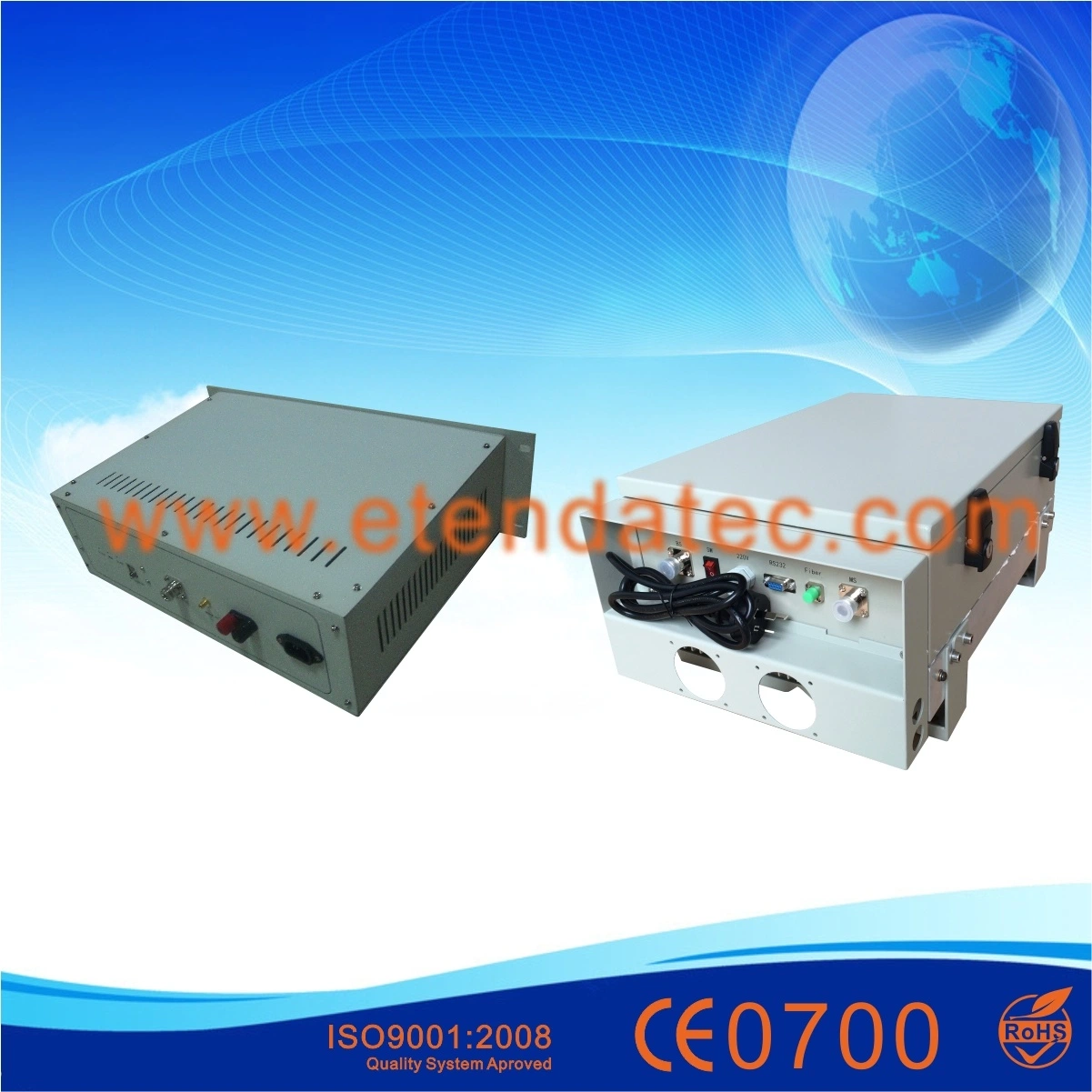
4. Product Image
Monitor Function1)Detection Function
Uplink and downlink attenuation; Uplink output power; Optical communication module status; The uplink and downlink output over-power and under-power threshold;Power amplifier switching; Downlink power amplifier status;
2)Control Function
Uplink and downlink attenuation; Downlink output threshold; The uplink and downlink output over-power and under-power threshold; Downlink VSWR threshold; Power amplifier switching; Channel setting;
Site SurveyBefore you install, the installer should contact the person responsible for the project, understand whether there are installed conditions in the installation site.
Specifically include: Installation site, surroundings (Temperature and Humidity), power supply, and so on. If qualified, should go live on-site survey with related personnel. The repeater is designed that can working outdoors, operating temperature is -25ºC~65ºC, humidity is ≤95%, which can be adapted to most areas of the natural environment.
Recommended Environmental Requirements:1.Installation area non-corrosive gases and fumes, Electromagnetic interference field strength ≤140dBμV/m(0.01MHz~110000MHz).
2.Mounting height should facilitate the RF cable routing, cooling, safety and maintenance.
3.Should provide a set of independent and stable 150VAC~290VAC(Nominal 220V/50Hz)AC Power. It must not be shared with other high-power appliances telecommunications equipment.
4.Lightning protection devices must be installed in the building, and it should have sufficient strength and stability.
5.There are grounding bar in the vicinity.
Installation ToolsInstallation tool to use: Electric impact drill, iron hammer, pulleys, ropes, belts, helmets, ladders, screwdriver, hacksaw, knife, pliers, wrenches, compass, measuring tape, tweezers, electric iron, portable PC, 30dB directional coupler, spectrum analyzers, VSWR tester.
Repeater installation Fixed safety and reliability;
The interface is connected correctly;
Reliable waterproof sunscreen, tape winding direction from bottom to top, in order to facilitate drainage;
Fixed height in order to facilitate the operation and not easy to be destroyed;
The Donor unit and remote unit can use pole installation or wall installation. According to the structure size of the equipment, use steel wire or the expansion screw to fix the machine on the upright rod or a wall. Equipment bottom height is generally 1.2 meters.
Antenna and Feeder Installation and Precautions1.Installation of antenna systems requires experienced professionals to complete.
2.You can not install an antenna near power lines, which may be life-threatening.
3.All exposed joints must use self-adhesive waterproof tape and electrical insulation tape seal securely.
Optical Fiber Connection DescriptionThe Donor unit connect to the remote unit through the optical fiber, therefore, optical fiber jumper type selection is very important when connecting, If the fiber jumpers do not match each other, connection will cause the loss of optical signal of different degree, cause open station failure.
In general the repeater station in the engineering application, there are two types of connection terminal, one is called FC/PC, and the other is called FC/APC. The difference between them is the head types, PC type head connecting surface is flat, APC type connecting surface inclined 8 degrees tilt. In engineering, the simple discrimination method is to observe the connection head protective rubber sleeve color, green is APC, black is PC.
APC/FC and PC/FC connectors are connected to each other will cause the optical transmission loss more than 10 to 20dB, therefore, in the project, different color head connected is strictly forbidden. Conversion between the two types of joints can be realized only by the optical fiber jumper.
Connect the Ground and Power Supply1. Equipment Grounding
The equipment must be well grounded, there is a copper on the repeater wall chassis ground, use 4mm2 or thicker copper wire close to the ground. Grounding wire should be as short as possible.
When installed, the equipment grounding wire should be connect to the integrated grounding bar. Grounding resistance of requirements bar may be≤ 5Ω, ground connector require preservative treatment.
2. Connect the Power
Connect 220V/50Hz AC power to the equipment power port terminal blocks, power line use 2mm2 cables, length less than 30m. For standby power requirement, the power must go through UPS, and then connect the UPS to the repeater power port terminal blocks.
For more details,feel free to contact us!

 Complaint