Description
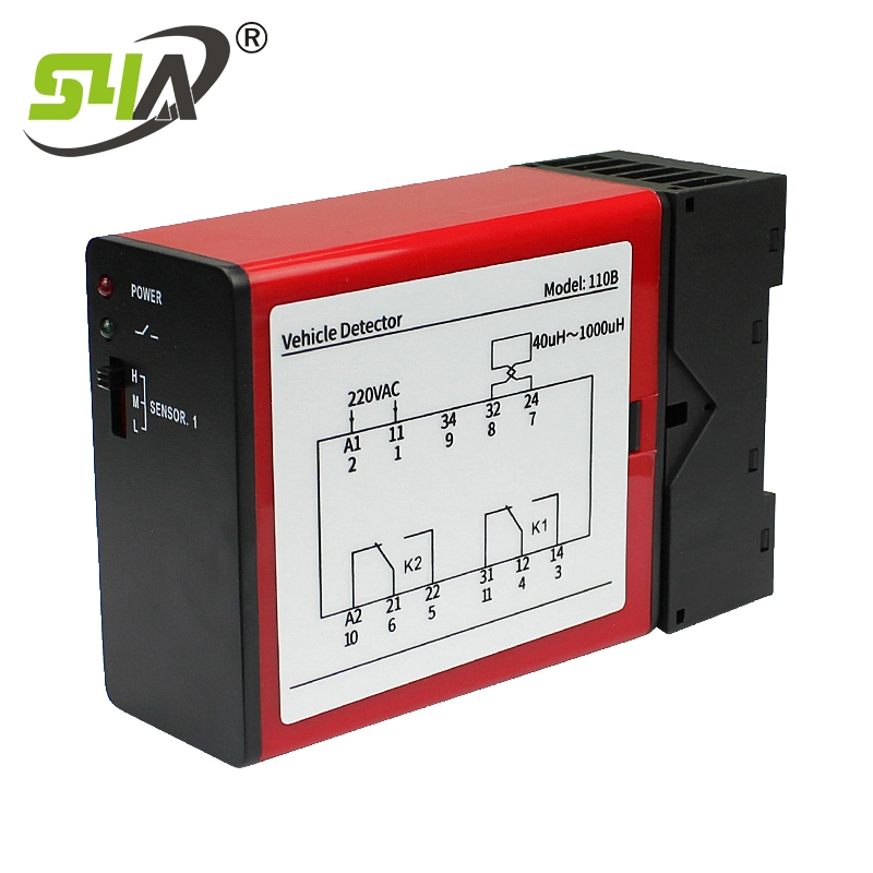
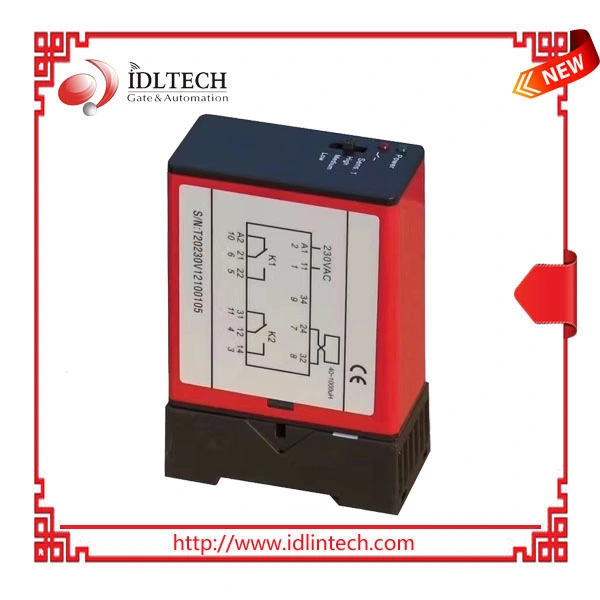
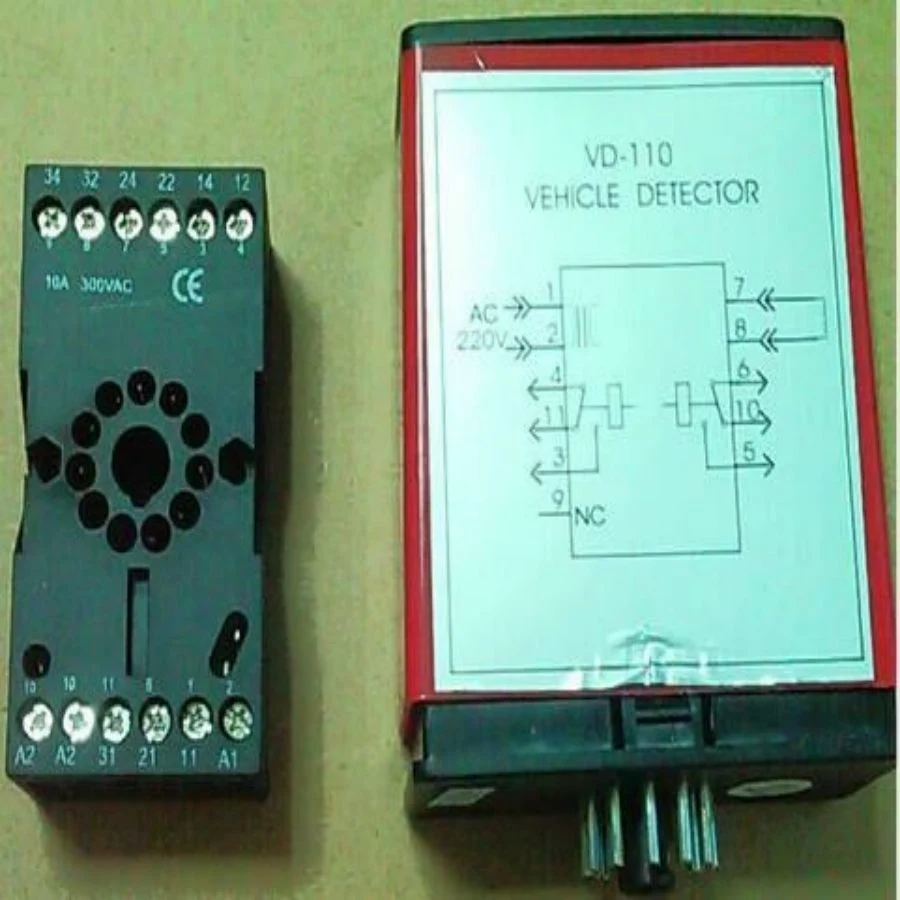
Install Detector Wiring Diagram
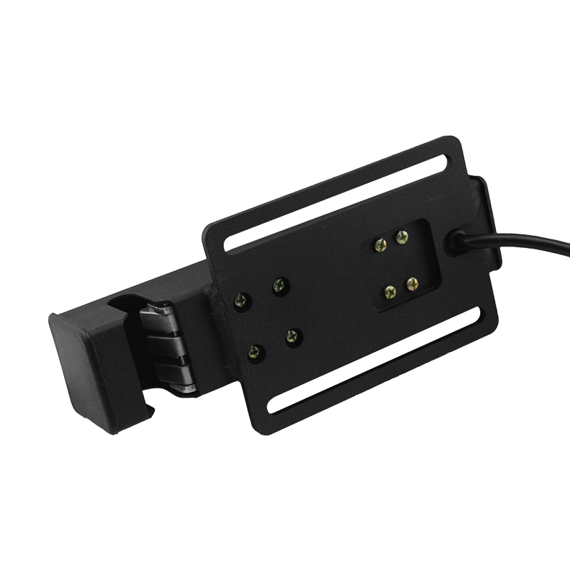
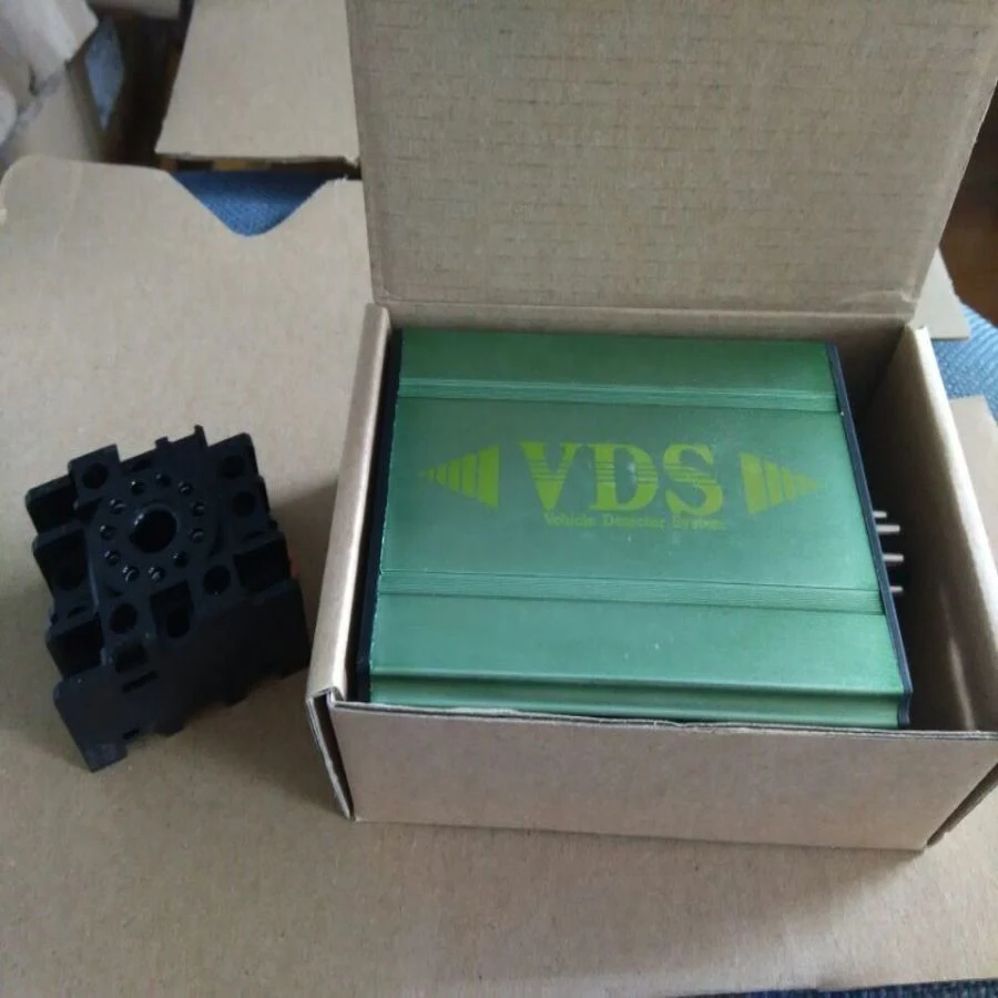
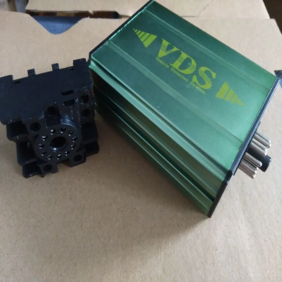
Theloop detectors must only be placed in dry rooms or control cabinets that are protected against all types of moisture and wetness. A distance of at least (10-20) mm from other devices must be maintained on each side. The ambient temperature must not exceed 55°c. The installation of the induction loop is described in other operating instructions.
Operation and Indication
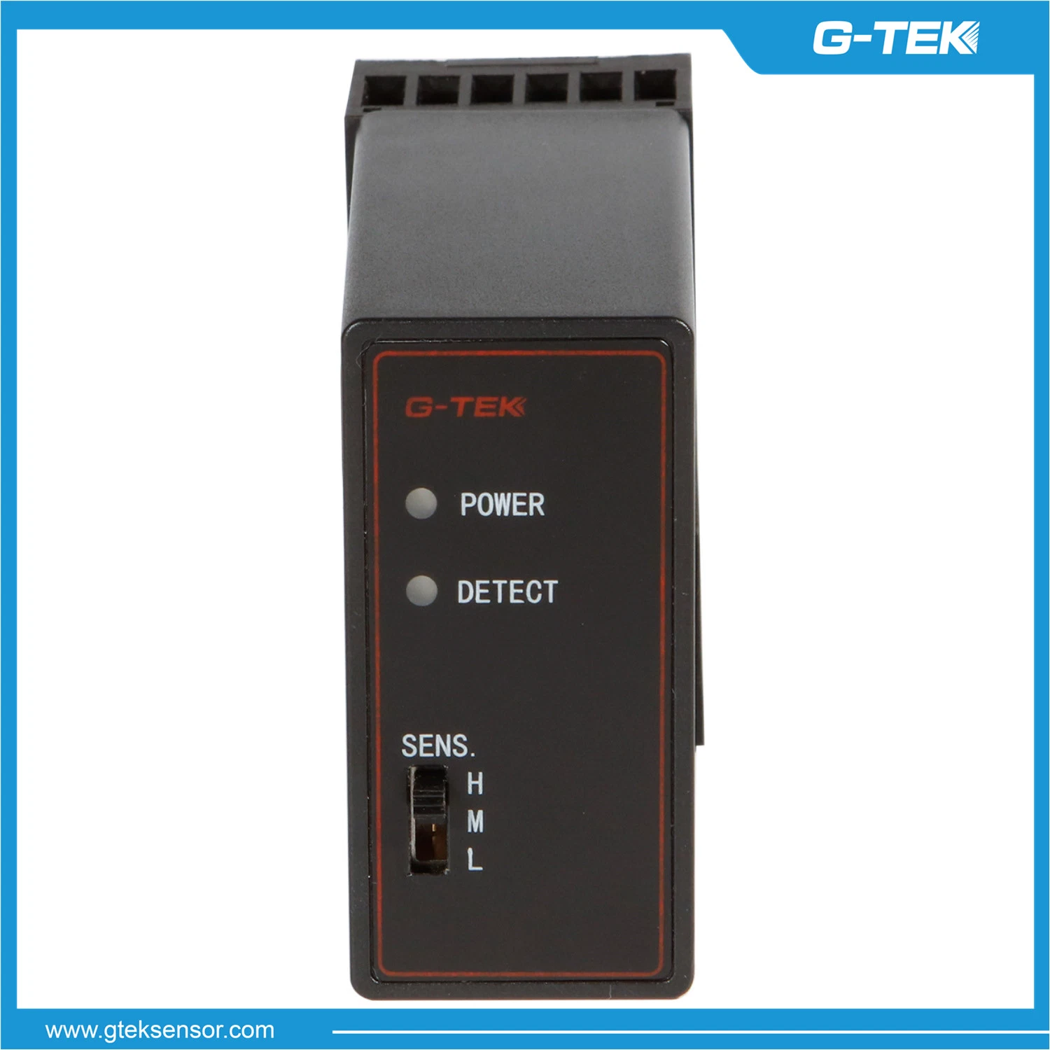
Whenthe power is applied, the red Power LED will glow and the detector is tuning,the green Check LED blink about 3 seconds. The green LED will also glow whenever a vehicle is detected passing over the inductive loop. If a loop fault
exists the green LED will come on and flash indicating a fault.
Loopno connected: Loop too small:
Looptoo large:
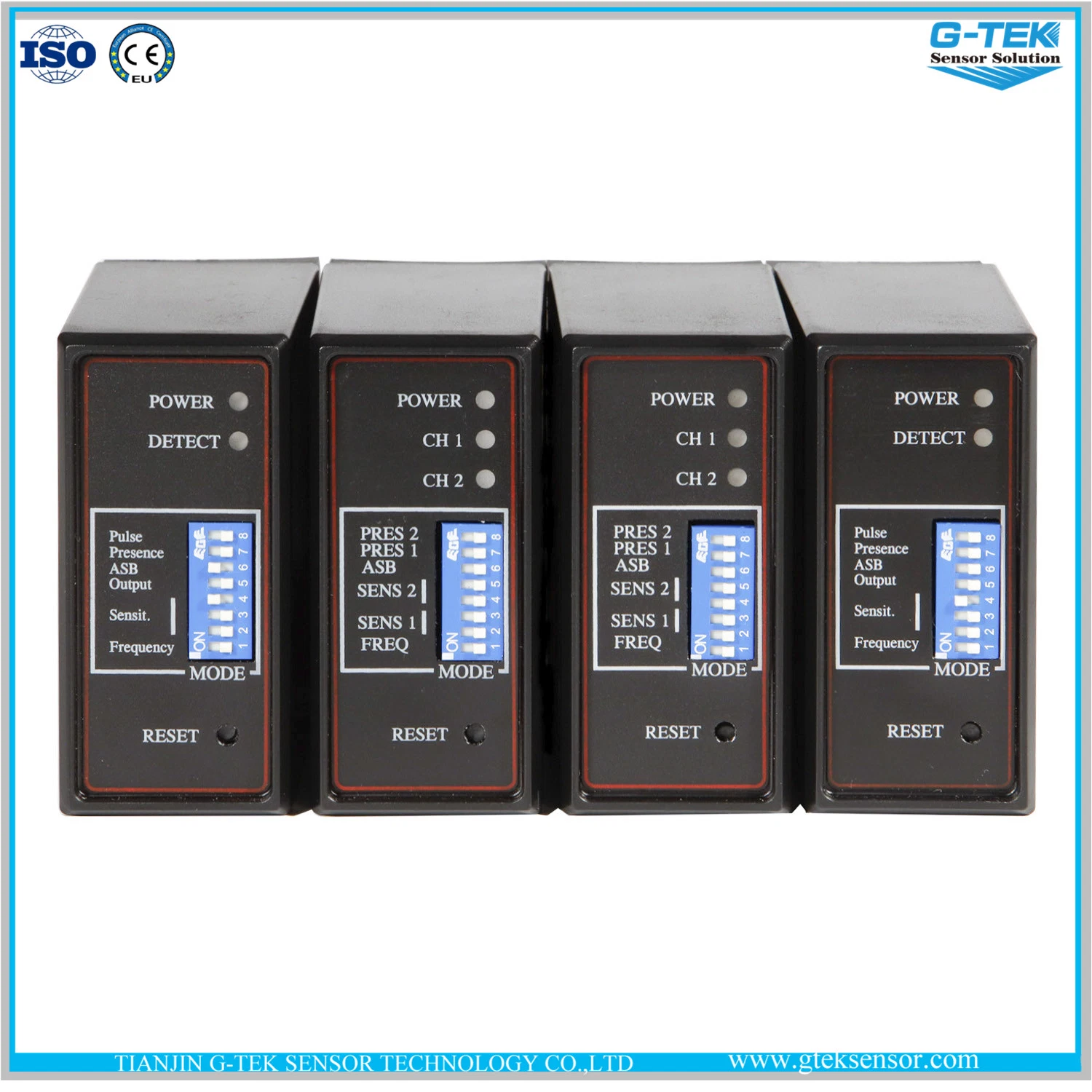
Frequency
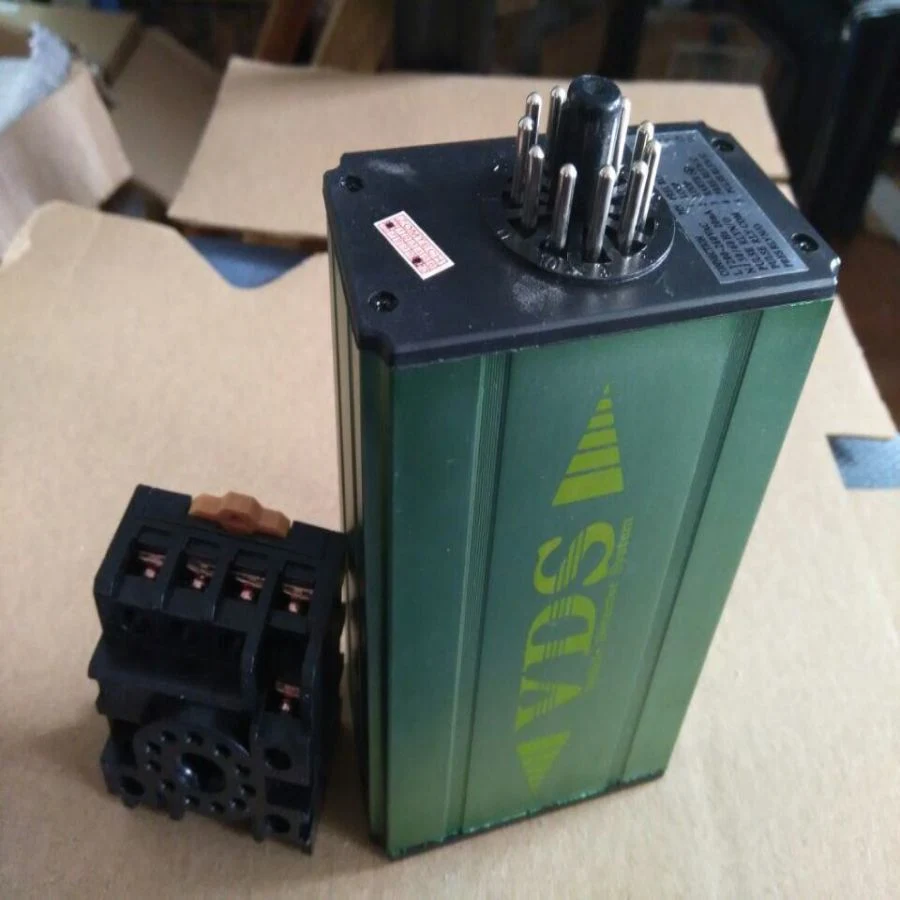
Thefrequency can be set by the two DIP switch on the circuit board. Disconnect power and then take down the detector from the socket, remove the shell. DIP6 (LA) is used for setting the frequency. ON: working in low frequency. OFF:working in high frequency The detector will be calibrated automatically when connecting the power after adjusting the frequency. Notice: High frequency has been set. The installation distance is too close between the two loop
detectors, the different frequency can be setting by the user.Sensitivity The response sensitivity can be set using the threestage switch on the front. The setting L corresponds to the lowest sensitivity. M is the medium sensitivity and H is the highest sensitivity. After the sensitivity has been set, a reset and a calibration automatically takes place.
Attention If thedetector isn't working normally, you must check the loop and wiring at first, and then alter the frequency or the sensitivity.
Output Relay
Whenvehicle press loop, the relay's output mode set by the main control panel switch. TLD-410 has two loops, corresponding to two output relays. loop1 (7-8 pin) corresponds to the relay 1 (5, 6, 10 pin) output for the existence of a fixed output signal, the loop 2 (7,9 pin) corresponds to the relay 2 (3,4,11 pin) and pull the output signal from the DIP code switch DIP1, DIP2, DIP3 (SW0,SW1, SW2) decision.Listen\Read phonetically.Vehiclepresence check model output setting Vehicle direction (count) check mode output signal and setting:
Reset
Thedetector automatically reset and tune to the inductive loop when the power is applied, whether on initial installation or after any break in power supply.Should it be necessary to retune the detector, as may be required after
changing any of the switches or after moving the detector from one installation to another.
Technical Data
Supply voltage: 230V AC , 115V AC, 24V DC/AC, 12V DC/AC
(See the label on the detector)
Voltage tolerance AC: +10% / -15%
Voltage tolerance DC: ±15%
Power Consumption: 4.5VA
Output relays: 240V/5A
Operating temperature: -20°c to +65°c
Storage temperature: -40°c to +85°c
Frequency range: 20 kHz to 170 kHz
Reaction time: 100ms
Signal holding time: Unlimited
Sensitivity:Adjustable in 3 increments
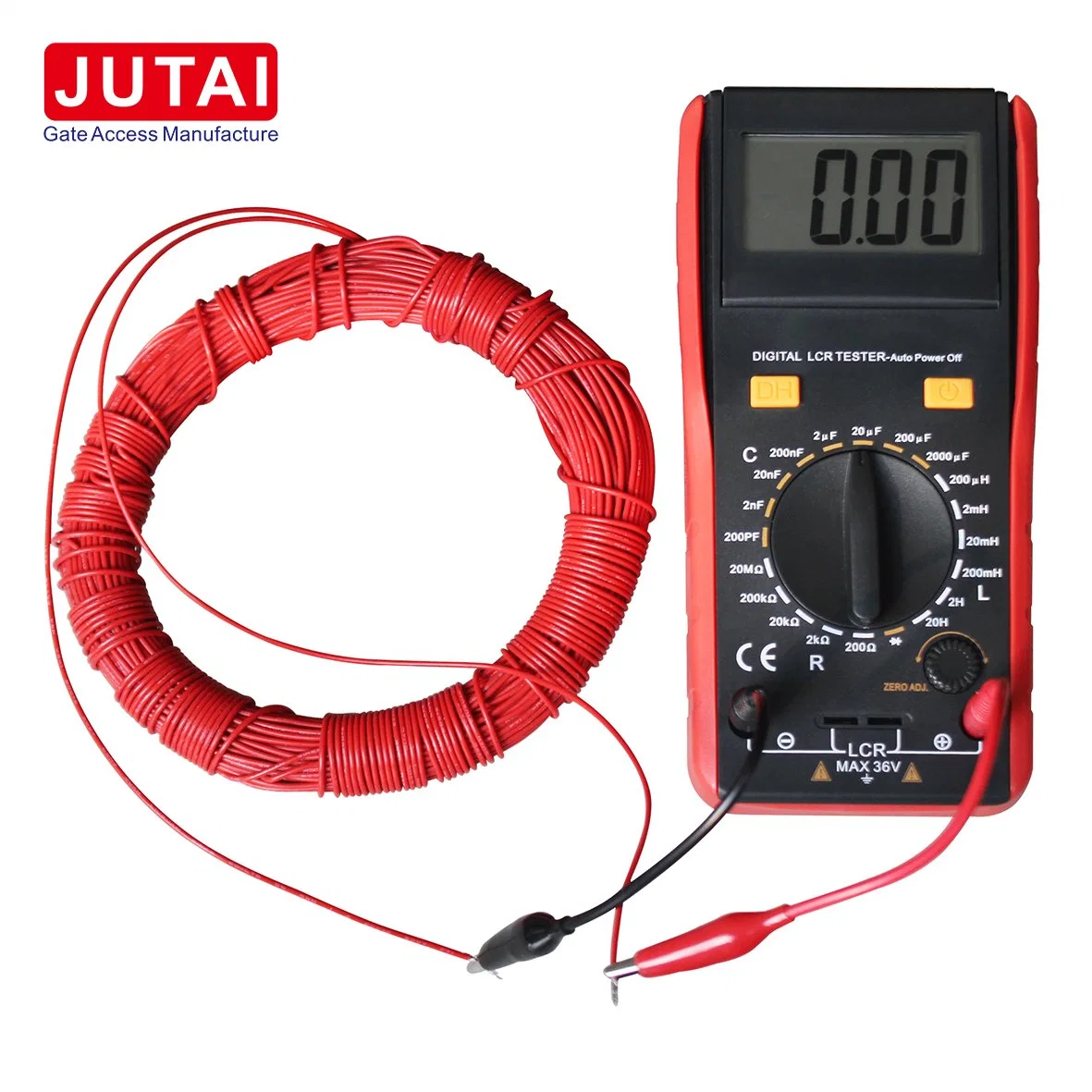
Loop inductance: Total loop plus connection wiring: 50μH to 1000μH.
Ideal is 100μH to 300μH
Loop connection wiring: Maximum length 20 meters, twistedat least 20 times per meter


 Complaint