


 Complaint

Overview:
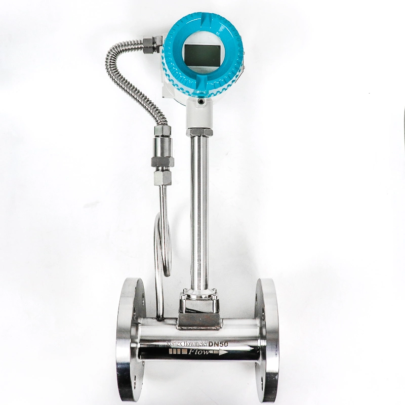
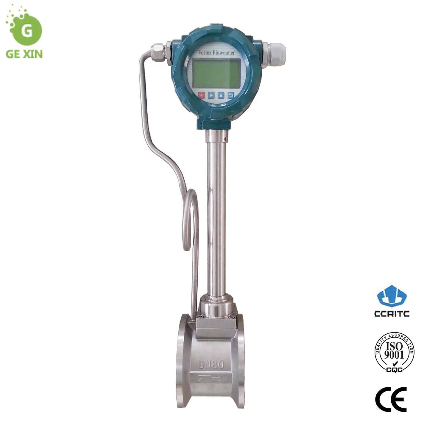
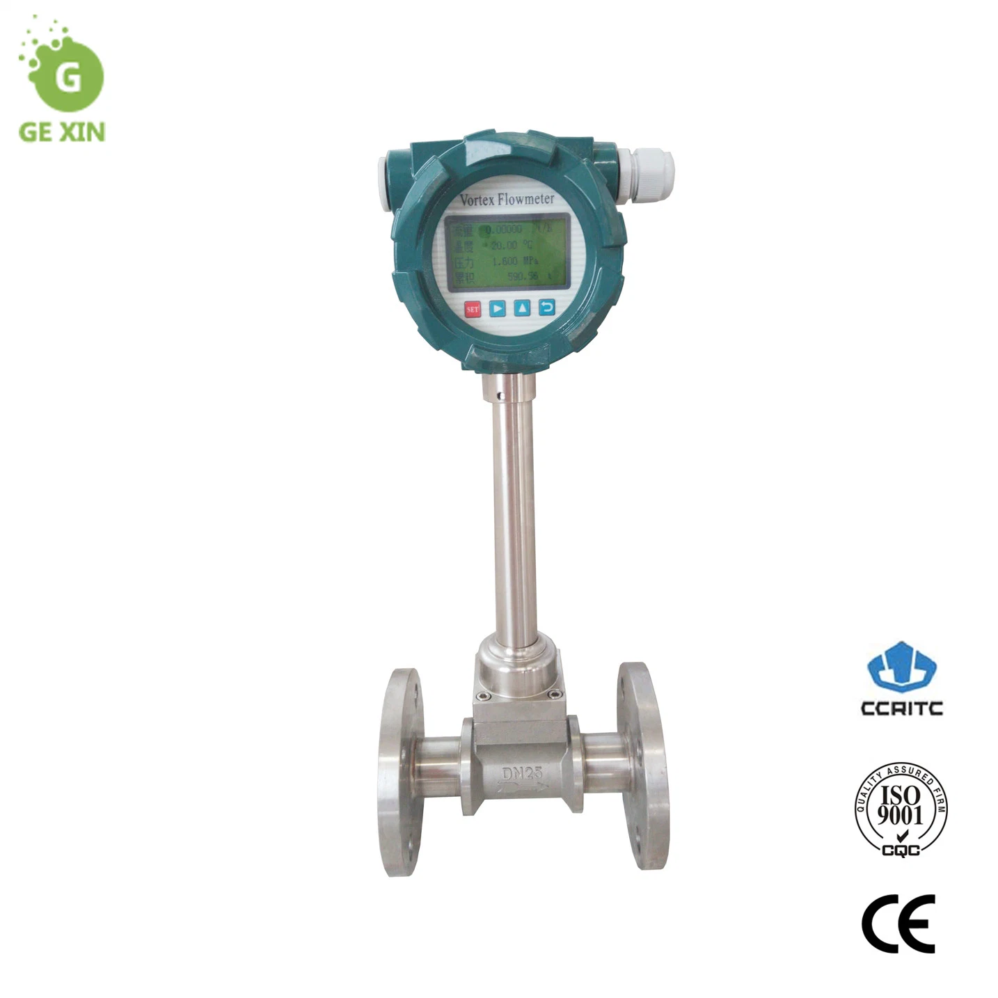
VF type vortex flow meter is widely used in the measurement and control of superheated steam, saturated steam, compressed air and general gas (oxygen, nitrogen, hydrogen, natural gas, gas, etc.), water and liquid (such as water, gasoline, alcohol, benzene, etc.) in petroleum, chemical, metallurgical, thermal, textile, paper and other industries.
Operating Principle:
In a fluid set bluff vortex generating body ( blocking fluid ), from both sides of the vortex generating body producing alternately two regular vortex, the vortex called Kaman vortex.
Vortex is arranged below the vortex generator non symmetrically.f:the vortex frequency,V: The average flow rate of the liquid,d: the width of the vortex generating body, D:the pipe diameter,Formula as below:
f=StV/d
formula parameter:
f-carmen vortex frequency
St-strouhal number
V-The average flow rate of the liquid
d-the width of the vortex generating body
Thus we could calculate the flowmeter according to the vortex frequcency.
In the curve St = 0.17 straight section, whirlpool release frequency and velocity proportional to, namely the vortex flow sensor measurement range. As long as the detected frequency f can be obtained within the tube by the flow rate of the fluid, flow velocity and volume flow rate V. The measured pulse number and volume ratio is called the instrument constant ( K ),see formula two
K=N/Q(1/m³)
definition:
K=constant(1/m³).
N=pulse count
Q=volume flowmeter(m³)
Medium:
Normal TEMP.:GAS,LIQUID(<100ºC)
MID TEMP.:GAS ,LIQUID, STEAM(100-250ºC)
Hight TEMP: GAS,LIQUID,STEAM(150-350ºC)
| diameter(mm) | 15,25,32,40,50,65,80,100,125,150,200,250,300,(300~1000 insert type) |
| pressure(MPa) | DN15-DN200 4.0(>4.0 customized),DN250-DN300 1.6(>1.6 customized) |
| temperature(ºC) | Piezoelectric type:-40~260,-40~320;capacitance type: -40~300, -40~400,-40~450(customized) |
| Body material | 1Cr18Ni9Ti,(customized if else material) |
| acceleration | Piezoelectric type:0.2g capacitance type:1.0~2.0g |
| accuracy | ±1%R,±1.5%R,±1FS;insert type:±2.5%R,±2.5%FS |
| span | 1:6~1:30 |
| Power supply | sensor:+12V DC,+24V DC;converter:+12V DC ,+24V DC;battery:3.6V |
| Output signal | Square pulse(not included battery):high level≥5V,low level≤1V;current:4~20mA;HART,RS485 |
| Pressure loss coefficient | Comform to the standard JB/T9249 Cd≤2.4 |
| Explosion grade | ex:ExdIIa CT2-T5 flameproof type:ExdIICT2-T5 |
| Protection grade | Normal IP65 scuba diving IP68 |
| environmentation | Temperature:-20ºC~55ºC,humidity:5%~90%,gas pressure:86~106kPa |
| medium | gas,liquid,steam |
| Trans distance | Pulse type:≤300m,current type: (4~20mA):load resistance:≤750Ω |
Reference conditions of vortex flow sensors flow rate range table
| DN (mm) | LIQUID | GAS | ||
| Volume range |
| Volume range | Frequency range | |
(m3/h) | (Hz) | (m3/h) | (Hz) | |
| 15 | 0.4~4 | 40~400 | 2.8~12 | 278~1190 |
| 20 | 0.7~7 | 26~260 | 6~30 | 226~1130 |
| 25 | 1~10 | 21~210 | 8.8~55 | 190~1178 |
| 32 | 1.5~15 | 15~150 | 15~140 | 150~1395 |
| 40 | 2.5~25 | 13~130 | 25~205 | 126~1036 |
| 50 | 3.5~45 | 9~119 | 35~350 | 93~930 |
| 65 | 5.5~75 | 6.7~91 | 60~600 | 73~730 |
| 80 | 8.5~110 | 5.3~68 | 86~860 | 53~530 |
| 100 | 16~180 | 5.2~58 | 130~1300 | 42~420 |
| 125 | 25~270 | 4.3~49 | 220~2200 | 38~380 |
| 150 | 35~350 | 3.3~33 | 350~3500 | 33~330 |
| 200 | 65~650 | 2.6~26 | 550~5500 | 22~220 |
| 250 | 95~950 | 1.9~19 | 850~8500 | 18~180 |
| 300 | 150~1500 | 1.8~18 | 1350~13500 | 16~160 |
| (300) | 150~1500 | 5.5~87 | 1560~15600 | 85~880 |
| (400) | 180~3000 | 5.6~87 | 2750~27000 | 85~880 |
| (500) | 300~4500 | 5.6~88 | 4300~43000 | 85~880 |
| (600) | 450~6500 | 5.7~89 | 6100~61000 | 85~880 |
| (800) | 750~10000 | 5.7~88 | 11000~110000 | 85~880 |
| (1000) | 1200~1700 | 5.8~88 | 17000~170000 | 85~880 |
In order to ensure a high measuring accuracy, the flow meter shall be horizontally installed on a horizontal pipeline, and the arrow sign on the flow meter that indicates the flow direction shall be made consistent with the liquid flow direction.In case a vertical installation is a must, the liquid shall be made flow from the down to top, so that the body of the flow meter will be ensured full of liquid.
To eliminate influences of the measuring accuracy resulting from uneven flow velocity distribution of cross section inside a pipeline, both the upperstream and the downstream of the flow meter shall be installed with definite straight lengths, or be installed with flow straighteners to substitute some straight lengths.
The small parts of the instrument are packed in cartons, protected by wrapping film, and the large parts are packed in export wooden cases