
 Complaint

| BCU instructions |
BCU module |
| User's Manual |
| [20178][V1.0] |
| parameter | Typical | Min | Max. | Unit |
| BCU supply voltage | 12V | 10 | 18 | V |
| BCU power consumption | / | / | 3 | W |
| SOC Estimation error | ±5 | 0 | 8 | % |
| Accuracy of current acquisition | 2 | 0 | 2 | % |
| Precharge | Support | / | / | / |
| Total Pressure Detection Range | 100 | 40 | 200 | V |
| Total Pressure Detection Accuracy | ±2 | ±5 | % | |
| Insulation Resistance Detection Range | 0 | 1000 | kΩ | |
| Insulation Resistance Detection Accuracy | ±5 | ±2 | ±8 | kΩ |
| Support slave BSU number | 2 | 1 | 16 | |
| Contact capacity of 6-way relay | 3 | / | 3 | A |
| 2-way Input Switching Signal Detection | / | 8 | 12 | V |
| 1-way RS485 communication | ||||
| 2-way CAN communication | ||||
| Working temperature range | / | -30 | 70 | ºC |
| Storage temperature | / | -40 | 85 | ºC |
| relative humidity | / | 40 | 95 | % |
| Anti-EMI Range | / | 150KHZ | 1000MHZ | HZ |
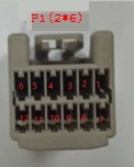
| Introduction of P1(2*6) pin Plug type:molex 64002-1215 Type of crimping terminal:molex 50654-1001 | ||||
| NO. | PN. | direction | Function description | parameter |
| 5,6 | POWER+ | Input | Host power supply interface | Input voltage range 8V~18V |
| 10,11,12 | POWER- | Input | ||
| 4 | P-12V | Output | Power Supply to Current Sensor | / |
| 3 | P+12V | Output | / | |
| 2 | ISensor | Input | Current Sensor Output Signal | -4V~+4V |
| 1 | PGND | Output | Ground of Current Sensor | / |
| 7 | CHG_P+ | Input | Charger + 12V | / |
| 8 | LCD_P+ | Output | Display screen power supply | / |
| 9 | LCD_P- | Output | / | |
| Introduction of P2(2*8) pins Plug type: molex 35563-1615 Type of crimping terminal: molex 50654-1001 | ||||
| NO. | PN. | direction | Function description | connection to |
| 8 | ISOSPI-L | / | Master-slave internal communication interface | BSU Minimum Serial Slave J1:4 IN_MI |
| 16 | ISOSPI-H | / | BSU Minimum Serial Slave J1:3 IN_PI | |
| 7 | T4+ | Input | Temperature Detection of Fast Filling Pin | / |
| 6 | T3+ | Input | / | |
| 15 | T4-/T3- | Input | / | |
| 14 | T1-/T2- | Input | Temperature Detection of Slow Filling Needle | / |
| 13 | T1+ | Input | / | |
| 12 | T2+ | Input | / | |
| 5 | LCD485-A | / | RS485 Communication Interface for Touch Screen | LCD_485_A |
| 4 | LCD485-B | / | LCD_485_B | |
| 3 | CAN1_GND | / | Vehicle CAN Communication Interface Matched 120_Resistor | CAN_GND |
| 2 | CAN1_L | / | CAN_L | |
| 1 | CAN1_H | / | CAN_H | |
| 11 | CAN2_GND | / | Charger CAN Communication Interface Matched 120_Resistor | CAN_GND |
| 10 | CAN2_L | / | CAN_L | |
| 9 | CAN2_H | / | CAN_H | |
| Introduction of P3 (2*10) pins Plug type: molex 35564-2015 Type of crimping terminal:molex 50654-1001 | ||||
| NO. | PN. | direction | Function description | parameter |
| 10 | K6COM | Output | Passive output of relay Permissible Charging: Closed No Charging: Disconnect | Charger Enablation |
| 20 | K6NO | |||
| 9 | K5OM | Output | Passive output of relay Allowed Motor Controller: Closed No Motor Controller: Disconnect | Motor Controller Enablation |
| 19 | K5NO | |||
| 8 | K4OM | Output | Passive output of relay Allowable Heating Relay: Closed No Heating Relay: Disconnect | Heating and refrigeration Control Relay |
| 18 | K4NO | |||
| 7 | K3OM | Output | Passive output of relay Precharging process: closure Precharge End: Disconnection | Precharging relay control |
| 17 | K3NO | |||
| 6 | K2OM | Output | Passive output of relay Allowable discharge: closure No Discharge: Disconnect | Discharge relay control |
| 16 | K2NO | |||
| 5 | K1OM | Output | Passive output of relay Permissible Charging: Closed No Charging: Disconnect | Charging relay control |
| 15 | K1NO | |||
| 4 | READY | Output | CHARG_READY | |
| 14 | SW1_G | Input | Input Switch Signal 1 Detection Ground | |
| 3 | SW1,SW2 | Input | High Detection of Input Switch Signal | |
| 13 | SW2G | Input | Input Switch Signal 1 Detection Ground | |
| 2 | AC-CP | Input | AC Charging Gun PWM Detection Interface | <=1KHZ |
| 12 | ON | Input | Start Switch Signal Detection Interface | +12V |
| 1 | CC2 | Input | DC Charging Gun Detection Interface | 4 V ~7 V |
| 11 | ACC-CC | Input | AC Charging Gun Detection Interface | 1 V ~9V |
| Introduction of P4(2*3) pins Plug type:molex 39-01-2030 Type of crimping terminal:molex 39-00-0077 | ||||
| NO. | PN. | direction | Function description | parameter |
| 1 | HV2+ | Input | Charging total | / |
| 2 | HV1+ | Input | Total load | / |
| 3 | BAT_HV+ | Input | Battery pack alignment | / |
| 4 | BAT_HV- | Input | Total negative battery pack | / |
| 5 | HV1- | Input | Total load | / |
| 6 | PG | Input | Frame ground | / |