Description
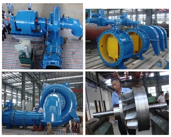
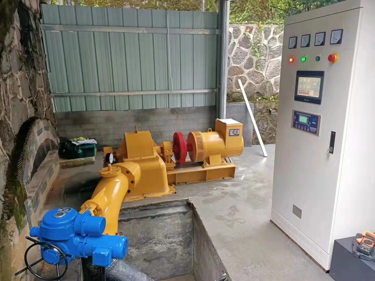
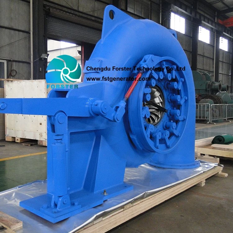
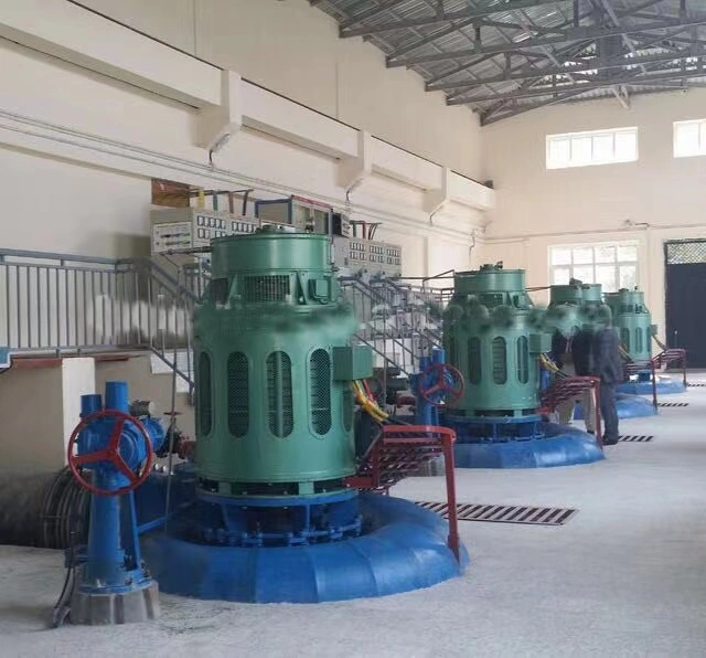
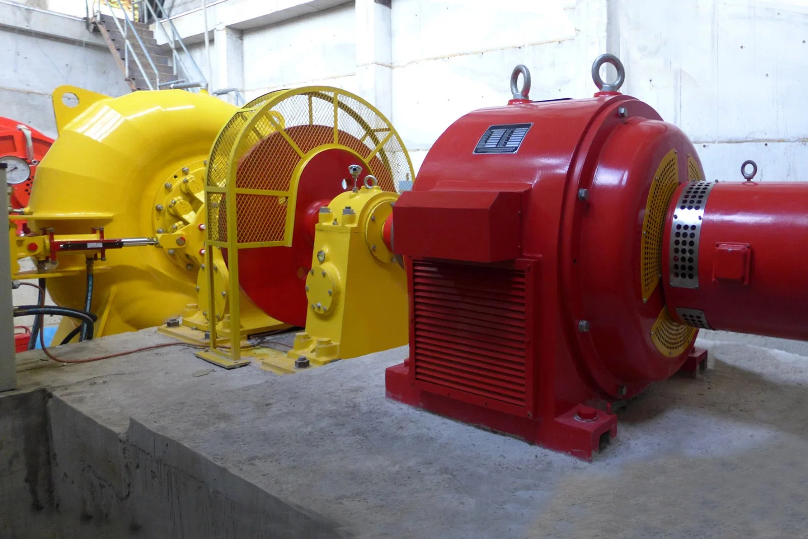
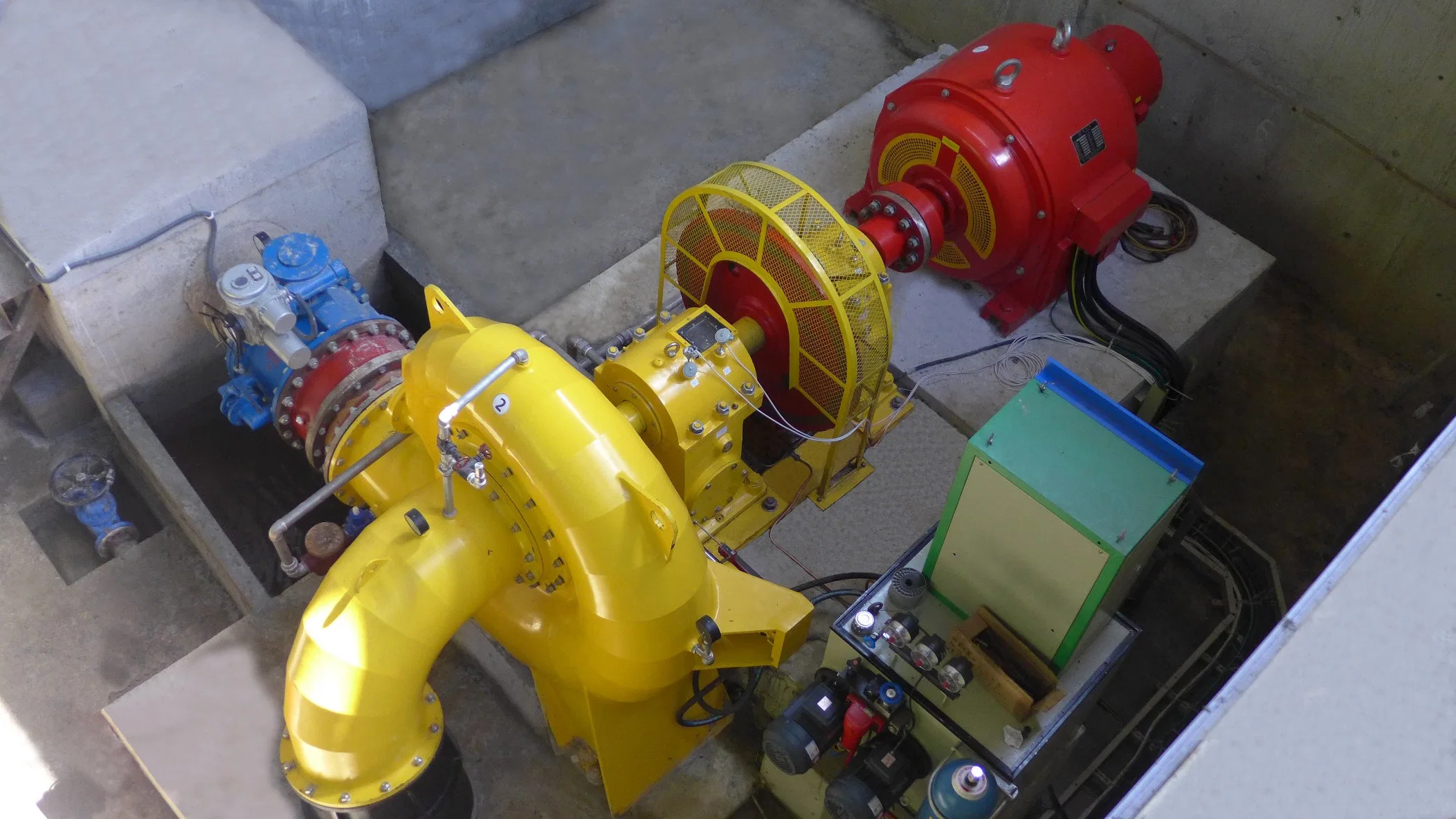
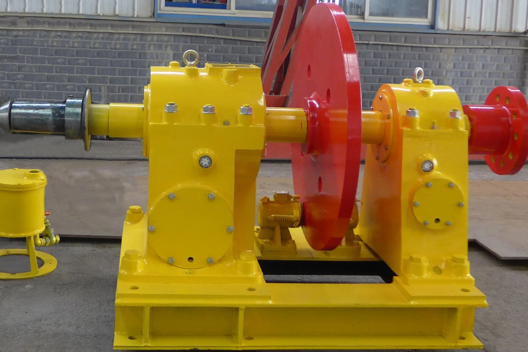
2X300KW Francis Turbine Generator UnitsFrancis Turbine Generator
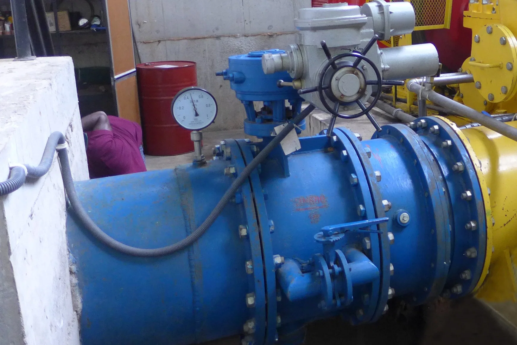
Main Inlet Valve (Butterfly Valve, motorized)
PLC hydraulic pressure automatic governor
Electric Control Panel (excitation, Synchronization, OC, OV, OF, UC, UV, UF Protection)
Table -1 Design Data
| Design Head m | 24 | Round Up Main Valve Diameter M | 0.9 |
| Design Flow m3/s | 1.6 | Turbine Model | HL360a-WJ-50 |
| Elevation m | 1307 | Generator Model | SFW300-8/850 |
| Runner Model | HL360a | Frequency Hz | 50 |
| Designed Unit Speed r/min | 75 | Min. Turbine Flow m3/s | 1.5 |
| Design unit Flow [m3/s] | 1.3 | Max. Speed Rise | 50 |
| Model Efficiency | 0.94 | Max. Pressure Rise % | 50 |
| Efficiency Revision | -0.01 | Specific speed mkw | 240.693 |
| Actual Turbine Efficiency | 0.93 | Unit runaway speed rpm | 140 |
| Generator Efficiency | 0.92 | Turbine Runaway Speed rpm | 1371.714 |
| Plant Output KW | 322.308 | First critical speed rpm | 1783.229 |
| Runner Diameter Calculation M | 0.501 | Generator Runaway speed rpm | 1480 |
| Round Up Runner Diameter M | 0.50 | Generator output Kw | 300 |
| Operation unit Flow [m3/s] | 1.306 | Generator Voltage V | 400 |
| Operation Unit Speed RPM | 76.547 | Power factor | 0.8 |
| Operation Turbine Discharge m3/s | 1.6 | Generator Current A | 541.282 |
| Turbine Output Kw | 350.335 | Excitation Current (A) | 188 |
| Generator Output Kw | 322.308 | Excitation Voltage (V) | 31 |
| Turbine Calculation Speed r/min | 734.847 | Model turbine max. efficiency % | 0.925 |
| Turbine Standard Speed r/min | 750 | Model turbine runner diameter m | 0.355 |
| Generator Standard Speed r/min | 750 | | |
| Generator Calculation Pole Number | 8.165 | Turbine Runner weight kg | 170 |
| Generator Standard Pole Number | 8 | Turbine total weight kg | 4500 |
| Axial Water Thrust Coefficient | 0.53 | Turbine heaviest part weight kg | 3700 |
| Axial Water Thrust 10kN | 2.498 | Turbine Max dimension (mm) | 1960*850*2100 |
| Cavitation Erosion | 0.013 | | |
| Allowed Suction height (H) m | 7.986 | Generator total weight (kg) | 3850 |
| Calculated Governor Power 10KN | 249.415 | Generator rotor weight (kg) | 960 |
| Round up Governor Power 10KN | 300 | Generator stator weight (kg) | 1680 |
| Excitation Panel | TKL | Generator heaviest part weight (kg) | 3850 |
| Calculated Main Valve Diameter M | 0.912 | Generator Max. dimension (mm) | 1850*1250*1350 |
Table -22.1 Spare parts for Turbine (per plant)| NO. | APPELLATION | UNIT | QTY | NOTE |
| 1 | Turbine Guide vane front bearing shell | pcs | 12 | |
| 2 | Turbine Guide vane middle bearing shell | pcs | 12 | |
| 3 | Turbine Guide vane back bearing shell | pcs | 12 | |
| 4 | Turbine guide vane seal ring | Set | 1 | 36 pcs |
| 5 | Turbine shear pin | pcs | 6 | |
| 6 | Pressure gauges (spiral case) | Set | 1 | |
| 7 | Pressure gauges (draft tube) | Set | 1 | |
| 8 | Pressure gauges (cooling water) | set | 1 | 600KW |
| 9 | Push button | Set | 1 | For governor |
2.2 Spare parts for Generator (per plant)| NO. | APPELLATION | UNIT | QTY | NOTE |
| 1 | Brake block | Set | 1 | |
| 2 | Brake oil seal ring | Nos | 6 | |
| 3 | Rotary Diodes | Nos | 3 | |
| 4 | Temperature sensor | Nos | 3 | |
| 5 | Radial Thrust Bearing radial Bushing | set | 1 | |
| 6 | Radial Thrust Pad | set | 1 | |
| 7 | Radial bearing bushing | set | 1 | |
| 8 | Thermometer (radial bearing) | Set | 2 | |
| 9 | Thermometer (thrust bearing) | Set | 1 | |
Table -3 Special Tools for Turbine
| NO. | APPELLATION | UNIT | QTY | NOTE |
| 1 | Rotor, flywheel dismantle tool | set | 1 | |
| 2 | Wrenches of all kinds | set | 1 | |
| 3 | Lift and Turning tool | set | 1 | |
Table -4
List of Automatic Components (per unit)| No. | Item | Model | QUANT | Measured position |
| 1 | Resistance thermometer | WZPD | 6 pieces | Measure Stator temperature |
| 2 | Resistance thermometer | WZP | 4 pieces | Bearing Oil temperature measure |
| 3 | Flow indication signaler | SLX | 2 pieces | Bearing Cooling water outlet pipeline |
| 4 | Shear pin transducer | JX-9 | 12 pieces | Water Distributor Mechanism |
| 5 | Vacuum Gauge | YZ-100 | 1 pieces | Draft tube Pressure monitoring |
| 6 | Pressure Gauge | Y-100 | 3 pieces | Spiral case, Bearing Cooling water inlet pipeline |
Table -5Excitation and Synchronization and Protection Panel | NO. | ITEM | MODEL | DESCRIPTION | QTY |
| 1 | Excitation, Synchronization and Protection Panel | TLK-1W/M
(300KW) | Generator excitation circuit:
LC-2 brushless excitation controller:
IGBT based smart control, full automatic voltage control, free from HF and MF harmonic interference, wide excitation voltage control and high stability. (especially for <15V ultra low voltage brushless excitation)
Multiple operation mode: 1. Automatic constant power factor mode after synchronization (Grid voltage tracking); 2. Automatic constant voltage mode at independent operation; 3. Island operation for small network; 4. Automatic voltage restore after tripping off, 5. Automatic de-excitation during shut down;
Generator Synchronization Control Circuit:
1. DW15-1000A Air Circuit Breaker
2. HD13-1000A Knife Switch
3. Generator PT/CT, 0.4KV Bus bar PT
4. ZTQ-8 Microcomputer Automatic Synchronization Device
5. Normal measuring meters for voltage, current, frequency, power factor.
6. Temperature data logging device, 1 set
7. GLB-2 generator protection device, 1 set,
Provide include over voltage, under voltage, over load, over current, short circuit, under frequency, over frequency and loss of voltage protection.
Power Plant Automatic Operation Control:
ZK980 Smart Integrated Controller
A microcomputer based automatic controller for hydropower equipment with touch screen interface and RS485 internet connection for monitoring and setting.
Provides automatic start/stop of turbine generator, automatic data measuring, alarm and protection action.
Main control function include: Automatic start, automatic speed control, automatic synchronization, adjust active power by the water level, reactive power automatic control, 8 line temperature display, alarm and relay, overspeed protection, electric protection during operation, automatic shutdown, automatic startup by water level, constant water level operation and communication functions.
8. GGD full enclosure cubicle | 1 set |
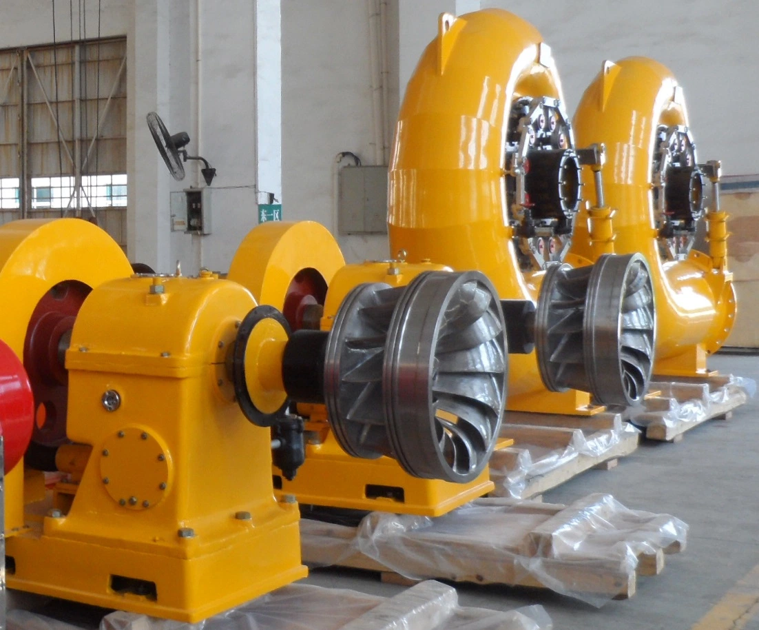
III. Main Parameters and Characteristics of Supplied Equipments- Water Turbine
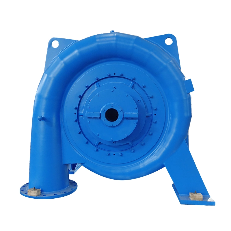
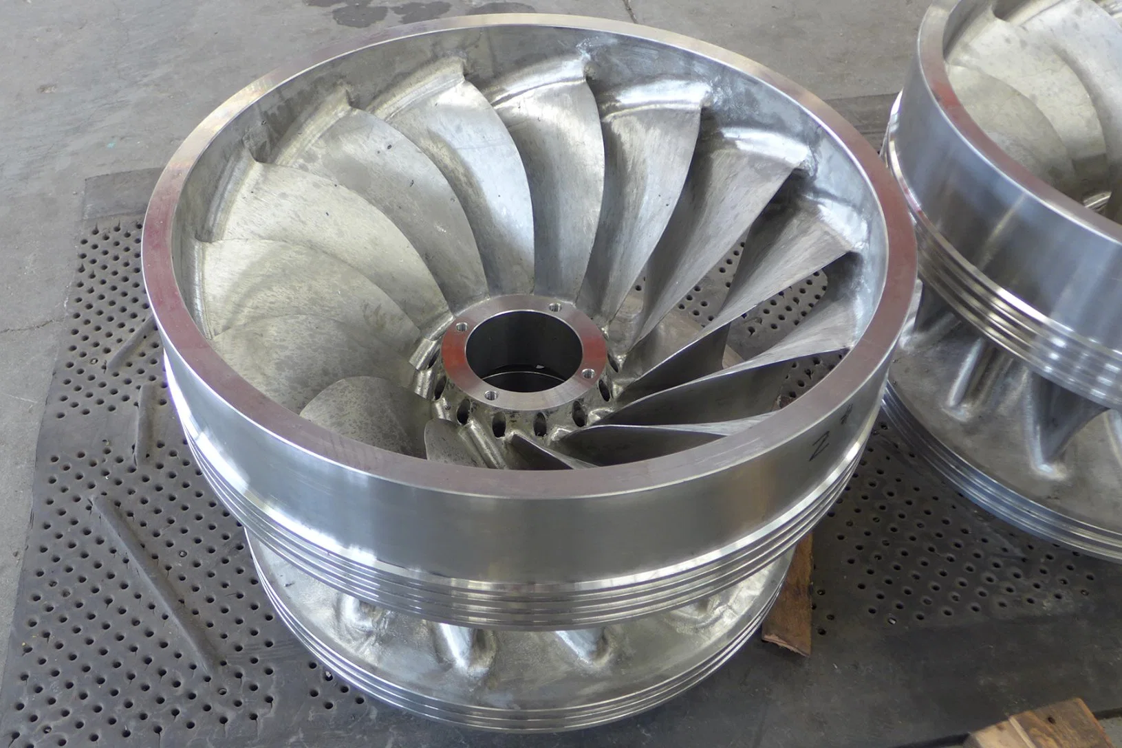
Horizontal Shaft Francis Turbinei.) General Description of the Francis TurbineA Francis turbine consists of three major parts, the spiral case, the water distributor and the runner. the flow enter the water distribution mechanism from penstock, through MIV, expansion joint, spiral case. by the open and close of the wicket gate in the water distribution mechanism, thus control the flow into the turbine. The water enters the runner evenly and drives the runner to convert the water energy into mechanical energy, and transmit through the main shaft to drive the generator rotor to rotate and then the generator converts the mechanical energy into electric energy.1). Water inlet structure: consists of inlet valve, expansion joint, etc. the inlet valve is to cut off the water in case of shut down the unit. it can also be used to emergently close the water in case of the unit accident and failure of the water distribution mechanism. The expansion joint is used to compensate the installation tolerance, and facilitate the install and dismantle of the MIV, it connect the spiral case at one end, to convey the water into the spiral case.2). Spiral case: the spiral case is weld structure with steel board and stay rings, the wicket gate are fabricated in the stay rings. The spiral case forms a circular water flow, guide the flow evenly enter the water distribution mechanism and runner in circular direction. There is a valve at the top of the spiral case, to discharge the air when fill up the spiral case in start-up procedure; a drain valve is provided at the bottom of the spiral case, to drain the water in case of shut-down repairs. 3). Water distribution mechanism: consists of front cover, back cover, guide vanes, guide vane sleeves, etc. Its function is to form and change the circular rector, thus regulate the flow, to match the load change. It is also used to shut down the turbine in normal operation. The guide vane is supported by axis sleeves. The axis sleeves are sealed with O shape seal rings.4). Runner: the runner the heart of the turbine, it converts the water energy into mechanical energy. The runner consists of upper crown, lower band, runner blades, combined by means of welding. The material can be customized according to client requirements. The runner is mounted on the generator shaft by cone shape and torque is transmitted by key. There are pressure discharge hole on the cone hub, to reduce the axial water pressure. There are seal ring on upper crown and lower band to reduce the leakage.
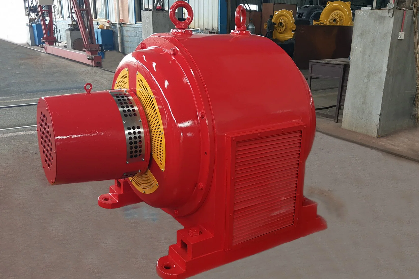
5). The daft tube consists of draft connection tube, bent tube, straight cone tube. Its function is to lead water down the stream, using the potential energy of the flow under suction height, and collect the kinetic energy of the flow left over from the outlet of the runner. All connected flanges of the draft tube should be sealed. The outlet of the cone tube lower end should be submerged with less than 400mm under water, to prevent air enter into the draft tube. There is air admission device on the draft connection tube to reduce the machine vibration.6) Speed regulation system: consists of governor, servomotor, regulation ring, etc. the governor control the servomotor, regulation ring, to adjust the opening of the wicket gate according to load change, so the turbine output matches the outside load change. When the governor was set at automatic position, if the turbine run away, it will automatically close the guide vane to empty load position and then the turbine can be shut down manually.3. Turbine Generator Parameters and Characteristics1. Model: HL360a-WJ-502. Runner Diameter: 500 mm3. Maximum head: Hmax=35 m4. Rated Head: Hr=24 m5. Min. Head: Hmin=20 m6. Design Flow: Qr=1.8 m3/s 7. Rated Output 350 KW8. Rated Speed: 750 rpm9. Runaway Speed: 1370 rpm10. Allowed Suction height: +7.98 m (guide vane height center line to normal tail water level)11. Rotation Direction: clockwise direction if viewed from the generator end12. Max axial water thrust: 2.49 ton 13. At design water, design flow and rated speed, the turbine rated output will be no less than 350KW, turbine efficiency at designed operation point will be no less than 94.0%, max operation efficiency is no less than 94.5%.14. Efficiency Guaranteed Value is as per the efficiency curve.15. The Noise level at 1 meter distance from the turbine spiral case does not exceed 85dB(A).16. Type: Turbine I horizontal Francis turbine, share main shaft with the generator.17. Cavitation erosion guarantee: during 8000hour operation period (among which less than 45% rated load operation time does not exceed 500 hour, above 100% rated load operation does exceed 100 hour), the weight loss on runner, guide vane, etc, flow contact part will not exceed 0.8kg.18. Stable Operation Guarantee:Given operating between minimum and maximum head range and 45% to 100% rated output range, suction head meet the design requirement, the Unit can operation at rated speed stably without causing excessive cavitation erosion.19. Guide Vane LeakageWith in 8000 hours since commercial operation, under rated water head, the turbine guide vane full close leakage will not exceed 0.3% of rated flow.20. Regulation GuaranteeIn case of dumping 100% load, the Unit maximum speed rise would not exceed 50%, spiral case maximum pressure rise will not exceed 50%, the designed wicket gate closing time does not exceed 8 seconds.21. Reliabilitya. In case of Runaway, if the runaway speed operation does note exceed 5 minutes, the Unit's components will not distorts.b. The time of turbine's first overhaul is 5 years from commercial operation, whole operation life is 40 years.22. Runner material is ZG0Cr13Ni4Mo.23. This turbine is 4-pedestal structure. The turbine has its own bearing, and the runner is over hung on the turbine shaft with the other end connect to the generator by a flexible coupler. The bearing is water internal cooling, self cycling lubrication structure, cooling water pressure is 0.25 to 0.3Mpa; The radial bearing is babbit alloy bushing, thrusting bearing is babbit alloy pads push against a round collar casted on the shaft.13. At design water, design flow and rated speed, the turbine rated output will be no less than 350KW, turbine efficiency at designed operation point will be no less than 94.0%, max operation efficiency is no less than 94.5%.14. Efficiency Guaranteed Value is as per the efficiency curve.15. The Noise level at 1 meter distance from the turbine spiral case does not exceed 85dB(A).16. Type: Turbine I horizontal Francis turbine, share main shaft with the generator.17. Cavitation erosion guarantee: during 8000hour operation period (among which less than 45% rated load operation time does not exceed 500 hour, above 100% rated load operation does exceed 100 hour), the weight loss on runner, guide vane, etc, flow contact part will not exceed 0.8kg.18. Stable Operation Guarantee:Given operating between minimum and maximum head range and 45% to 100% rated output range, suction head meet the design requirement, the Unit can operation at rated speed stably without causing excessive cavitation erosion.19. Guide Vane LeakageWith in 8000 hours since commercial operation, under rated water head, the turbine guide vane full close leakage will not exceed 0.3% of rated flow.20. Regulation GuaranteeIn case of dumping 100% load, the Unit maximum speed rise would not exceed 50%, spiral case maximum pressure rise will not exceed 50%, the designed wicket gate closing time does not exceed 8 seconds.21. Reliabilitya. In case of Runaway, if the runaway speed operation does note exceed 5 minutes, the Unit's components will not distorts.b. The time of turbine's first overhaul is 5 years from commercial operation, whole operation life is 40 years.22. Runner material is ZG0Cr13Ni4Mo.23. This turbine is 4-pedestal structure. The turbine has its own bearing, and the runner is over hung on the turbine shaft with the other end connect to the generator by a flexible coupler. The bearing is water internal cooling, self cycling lubrication structure, cooling water pressure is 0.25 to 0.3Mpa; The radial bearing is babbit alloy bushing, thrusting bearing is babbit alloy pads push against a round collar casted on the shaft.24. Turbine spiral case water inlet direction is horizontal inlet. Automatic air admission device is provided on the bend tube. iii.) Design Features to notice:1. Easy to adjust regulation ring mechanism:Each wicket gate (guide vane) position (opening) can be adjusted separately, to achieve tight closing seal, thus minimize the water leakage.This design also makes the repairs and maintenance much easier after a long time of operation, so the guide vane can still provide tight water seal.2. Quick Clean Window:A quick clean window is provided on the spiral case, so there is no need to remove the front or back cover of the spiral case when foreign objects (stone, tree branches, clothes, etc) are blocking the wicket gate. Open the window is also simple, a green hand can also do the check and cleaning. For the same purpose, to open and assembly the spiral case front/back cover required very good skilled person and take much longer time.3. Non-contact Main Shaft Seal:Our main shaft adopts combined non-contact labyrinth and splash ring seal. The turbine main shaft does not contact with the spiral case cover. The shaft does not need to replace in whole life time. During the operation, there is hardly and water leak out from the main shaft hole.If using packing seal, the packing need to tighten and replace regularly, and main shaft will wear at the contacting point.4. Generator Parameters1. Model: SFW300-8/850 2. Rated Capacity: 300kW 3. Rated Voltage: 400V 4. Rated Current: 541.3.1A 5. Rated Power Factory: 0.8 (lag) 5. Rated Frequency: 50Hz 7. Phase Number.: 3 8. Rated Speed: 750 rpm 9. Runaway Speed: 1480r/min 10. Stator winding method: Y 11. Stator insulation class: F/F 12. Rotation Direction: clockwise direction if viewed from the generator end13. Designed Efficiency: 92% 14. Generator Performance:(1) Temperature Rise, according the GB standard, when cooling media temperature is 40ºC, stator's calculation temperature rise is less than 80K, rotor's calculation temperature is less than 85K.(2) Vibration and Swing does not exceed specification required value.(3) Noise: Not more than 85db according standard measuring method.(4) Ventilation Method: opening type ventilation15. Electric Characteristics Guarantee:a. when the stator winding is properly connected according to design method, in case of empty load at rated voltage, linear voltage wave harmonic distortion is no more than 5%.b. In case of empty load at rated voltage and rated speed, linear voltage "Telephone Harmonic Factor" (THF) does not exceed 3%.c. In hot state, generator could withstand 150% rate current for 2 minutes without causing harming distortion and weld crack, etc. The voltage at such point should be as close to rated as possible.d. In case the Generator is operating in asymmetric system, if non phase exceed rated current value, and negative phase current component vs rate current does not exceed 12%, the generator can long term operate safely. In case of asymmetric fault, in case I22·t<40, the generator is allowed to operate in short time, I2 is the average square root of the negative current in t second time (per unit value).16. Mechanical Performance Guarantee:a. Generator should be able to withstand maximum runaway speed for 5 minutes without causing harmful distortion. When the turbine generator unit dumping 100% load, given the governor system operate normally, the Unit is permitted to connect to Grid without any check.b. Under rated voltage or 105% rate voltage, the generator's mechanical strength could withstand stator terminal suddenly short circuited symmetrically or asymmetrically for 3 seconds without incurring harmful distortion.17. Structure Features and Technical RequirementsGenerator is horizontal, 4 pivots, roller bearing at both ends structure. Generator main shaft is coupled to turbine via flexible coupler. Generator consists of generator, rotor, end cover, brushless excitor, etc. the main bearing of the generator is two pieces of roller bearing at both end of the stator bracket.1). Stator Stator unit consists of Frame, Iron core, Winding, etc. Stator Frame is Q235 steel plate, stator Iron core is low loss, non-aging, high quality cool roll thin silicon steel laminated; stator winding conductor is annealed copper, with required conductivity.2). RotorRotor unit consists of Main shaft, Magnet yoke, Magnet pole and fans etc. Main shaft adopts 45# high quality steel, and complies with JB/1270 "Specification for shaft forgings hydro turbines and hydro generators" requirements. Magnet pole consists of Iron core, Magnet pole winding, upper and lower layer board, etc. Iron core is made from laminated1.5mm steel plate and.3). End Cover Front and Back End cover is foreseen, roller bearings are mounted in the end cover.4). Monitoring InstrumentsThere are six PT resistance embedded in the generator stator to detect temperature.5). Generator insulation class is F class.Standard and specification the Equipment complies:
GB/T15468-1995 Fundamental Technical Requirements for Hydraulic TurbinesGB/T10969-1996 Specifications for Water Passage Components of Middle and Small Hydraulic TurbinesGB7894-2001 Fundamental technical specifications for Hydro generatorsGB11805-89 Basic Technical Specification for automatic control components and their related systems for Middle and Small hydro generating setsJB/DQ1554-89 Middle and small hydraulic turbine Quality classificationJB/DQ3467-88 Middle and small hydraulic turbine Generator Quality classificationDL/T563-95 Hydraulic turbine electric and hydraulic regulation system and hydraulic pressure device technical specificationGB/T11352-89 Normal cast carbon steel for engineering useGB6969-86 Middle High strength stainless steel cast piece for engineering structureGB/T699-1999 Quality Carbon Structural Steels Technical Specification GB/T 1591-1994 High Strength Low Alloy Structural SteelsGB/T 1591-1994 High Strength Low Alloy Structural Steels GB/T 8162-1999 Seamless steel pipe GB/T5117-1995 Covered electrodes for manual metal arc welding of non-alloy and fine grain steelsGB/T 3098.1-2010 Mechanical properties of fasteners -Bolts, screws and studsGB/T983-2012 Covered electrodes for manual metal arc welding of stainless and heat-resisting steelsGB/T755--2000 Rotating generator, rating and performance GB/T1029-1993 Test procedures for three-phase synchronous machinesGB/T755--2000 Rotating generator, rating and performance GB/T1029-1993 Test procedures for three-phase synchronous machinesGB/T 1800.1-2009 Geometrical product specifications (GPS) - Limits and fits - Part 1: Bases of tolerances, deviations and fitsGB/T1804-1992 General tolerances for linear dimensions without individual tolerance indicationsGB 2649-1989 Methods of sampling for mechanical properties tests of welded joint GB 2651~2656-2008 Tensile test method on welded joints GB8564-2003 Specification installation of hydraulic turbine generator units GB/T 12222/12223 Multi-turn valve actuator attachmentsGB 4208 Degrees of protection provided by enclosure (IP code)GB/T 12238-2008 Flanged and wafer resilient seal butterfly valvesGB/T13927-92 General purpose valve - pressure testGB/T 9112-2010 Types and parameters for steel pipe flangesGB/T12227-2005 General purpose industrial valve-Specification of spherical graphite iron castingsGB/T 1047-2019 Pipework components -Definition and selection of nominal sizeGB 1094-1996 Power transformersJB/T 10318-2002 Specification and technical requirements for oil immersed amorphous ally core distribution transformerGB/T 6451-2015 Specification and technical requirements for oil-immersed power transformersJB/T8860-1997 Specification for turbine generator unit packing, transportation and storage2. Check and Test
The "supplier" must check, test and pre-assembly the equipments and major components in the factory according related technical standard and specification, to find out the quality and performance index complies with related requirements, properly adjust assembly part clearance, make matching mark or position pin, to ensure correct assembly on the site.All factory inspection items and ex-factory inspection items will generator inspection report and record.The turbine generator is different for every hydropower plant.
To make a customized quotation we need to make the model selection first.
Project data required for turbine generator model selection :
| 1 | Water Head | | (m) |
| 2 | Total Discharge | | (m3/s) |
| 3 | Discharge per turbine | | (m3/s) |
| 4 | Number of Units | | (set) |
| 5 | Generator Voltage | | (V) |
| 6 | Generator Frequency | | (Hz) |
| 7 | Grid Voltage | | (V) |
| 8 | Total installation capacity | | (KW) |
It would be great if you have a complete specification document for the machine requirement,
Our engineer will make their professional suggestion and advice.
The model selection service is completely free.
 Complaint