 Complaint

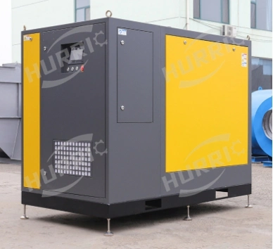
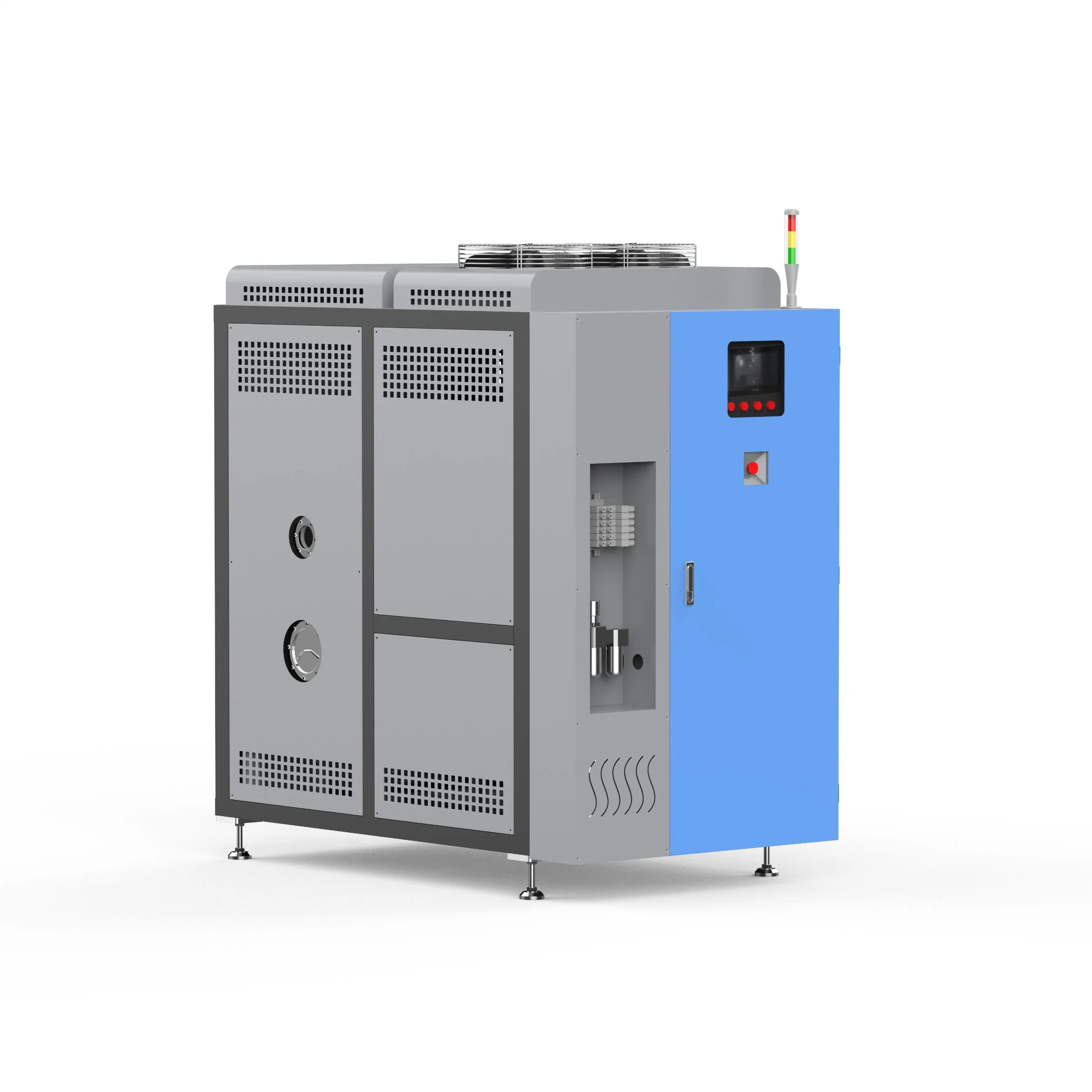
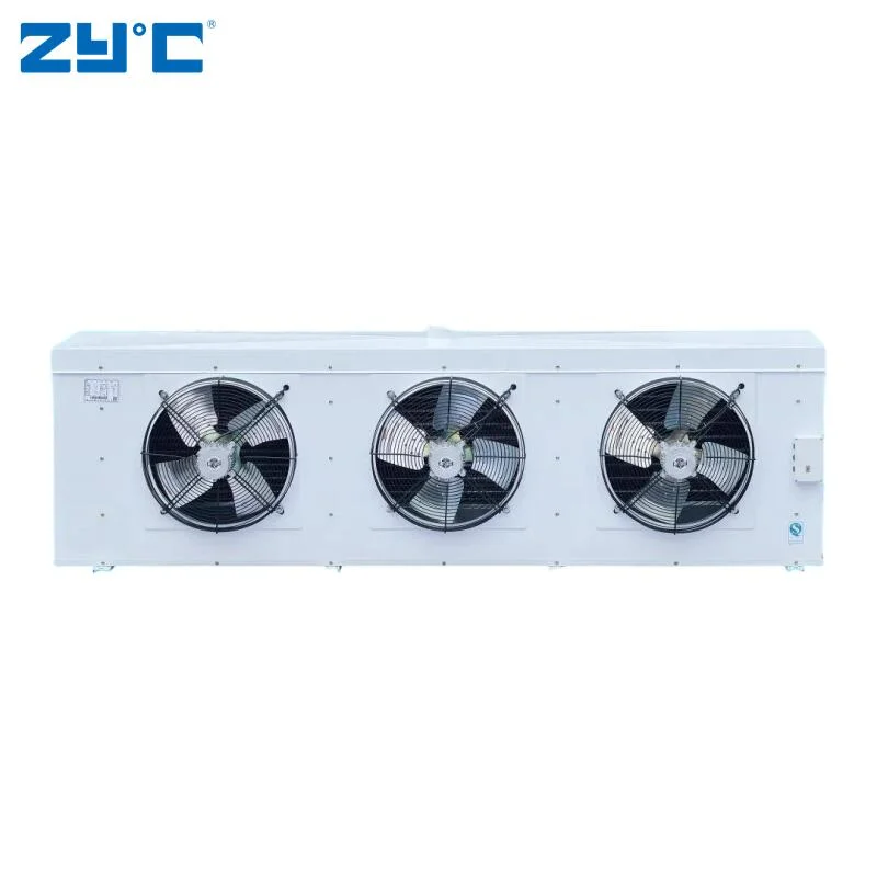
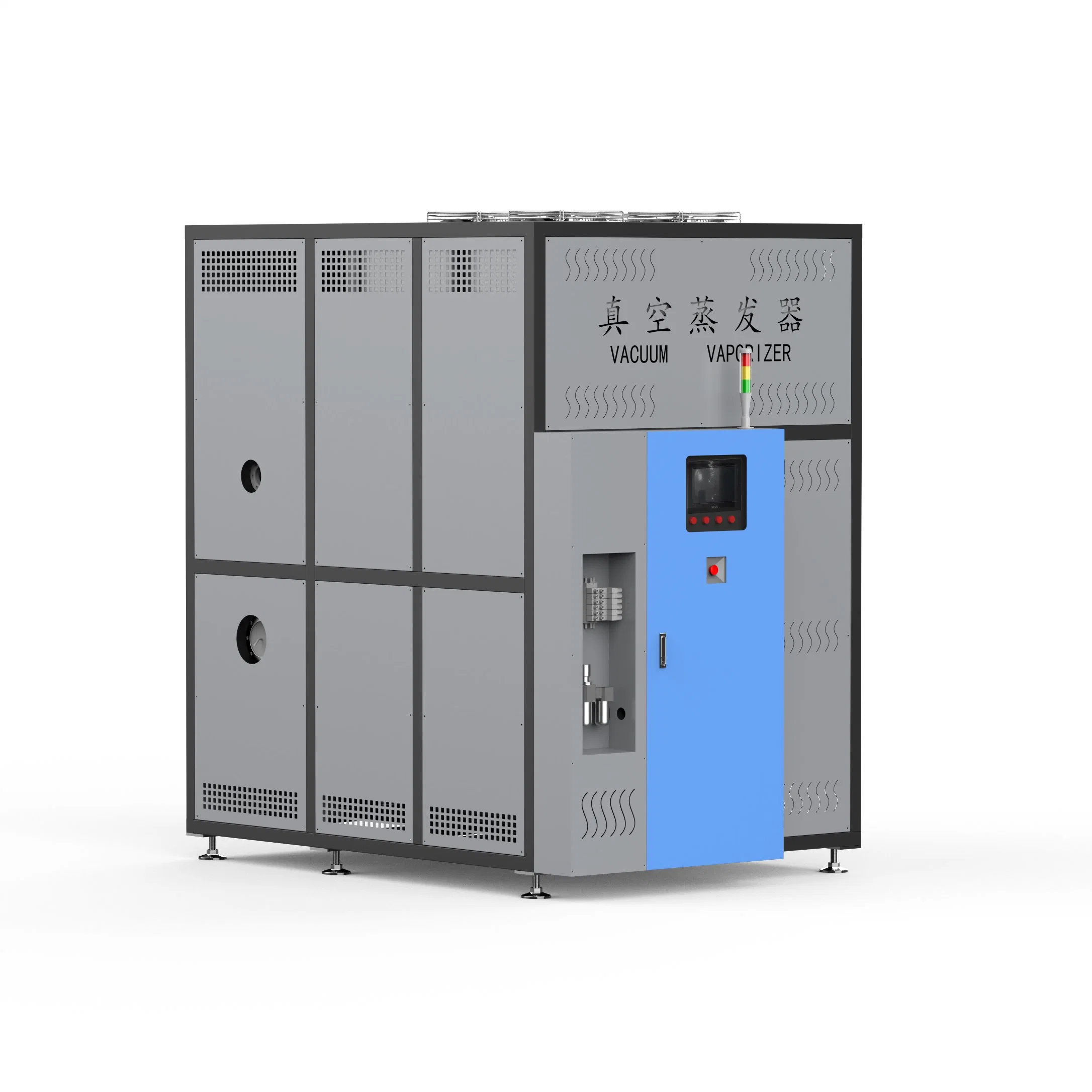
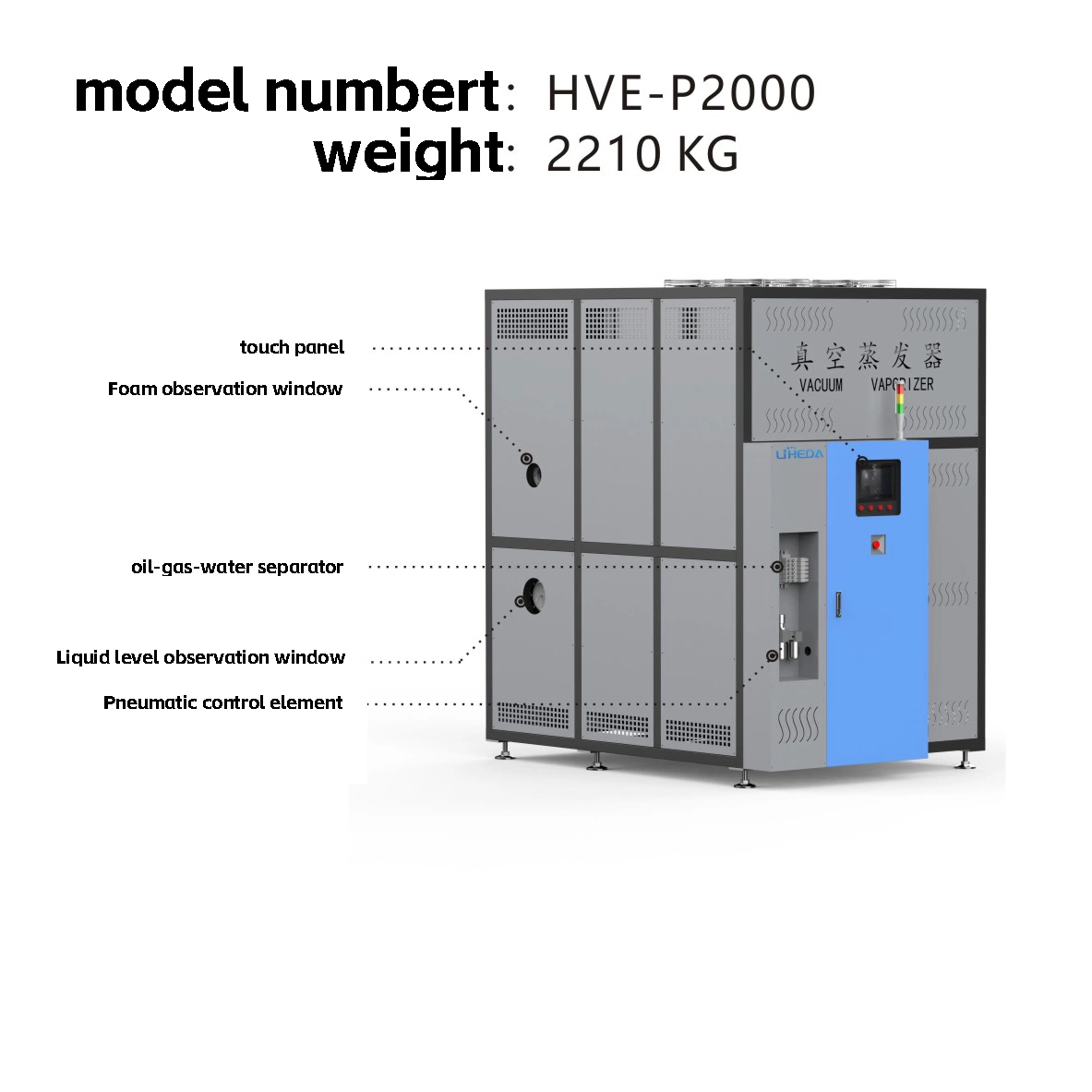
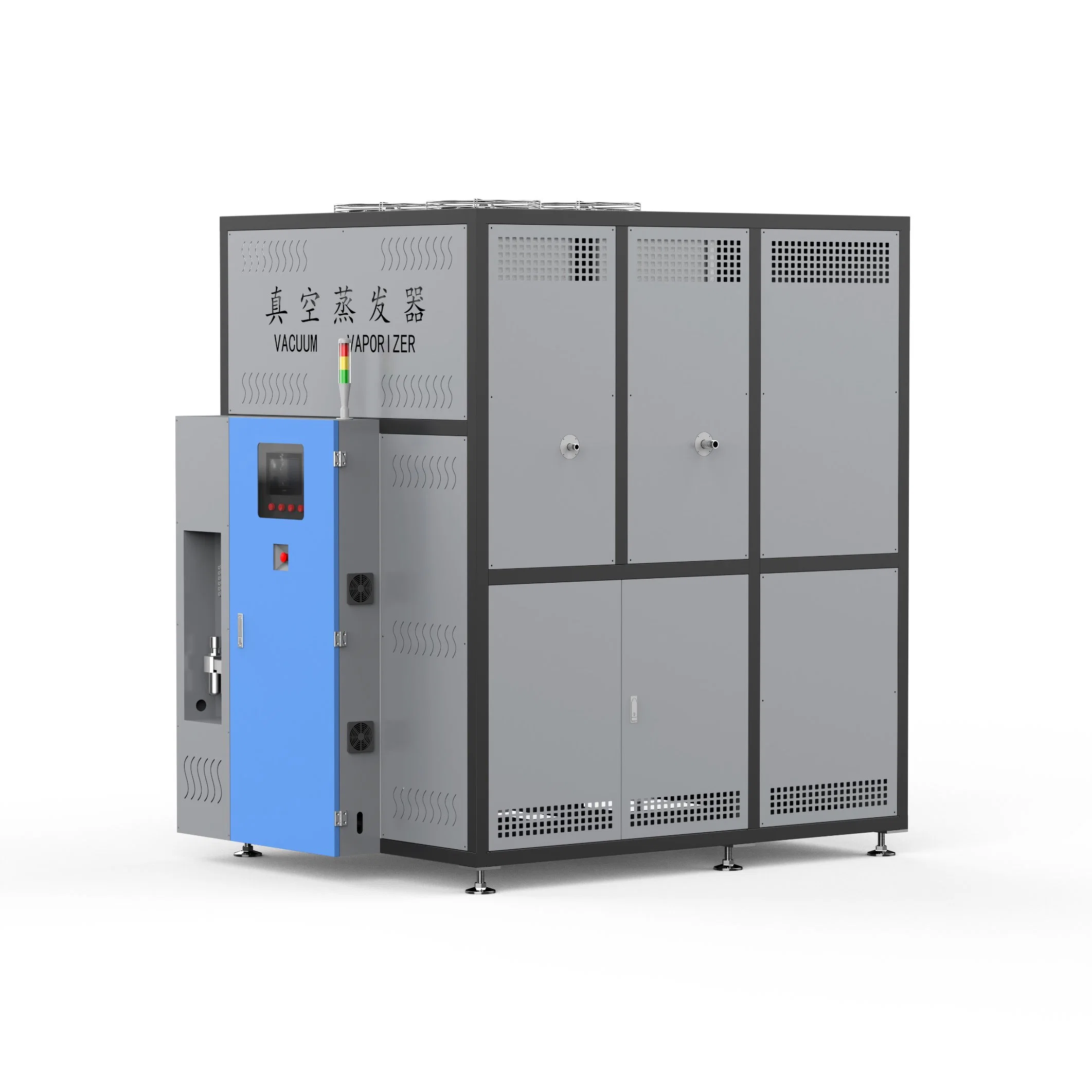
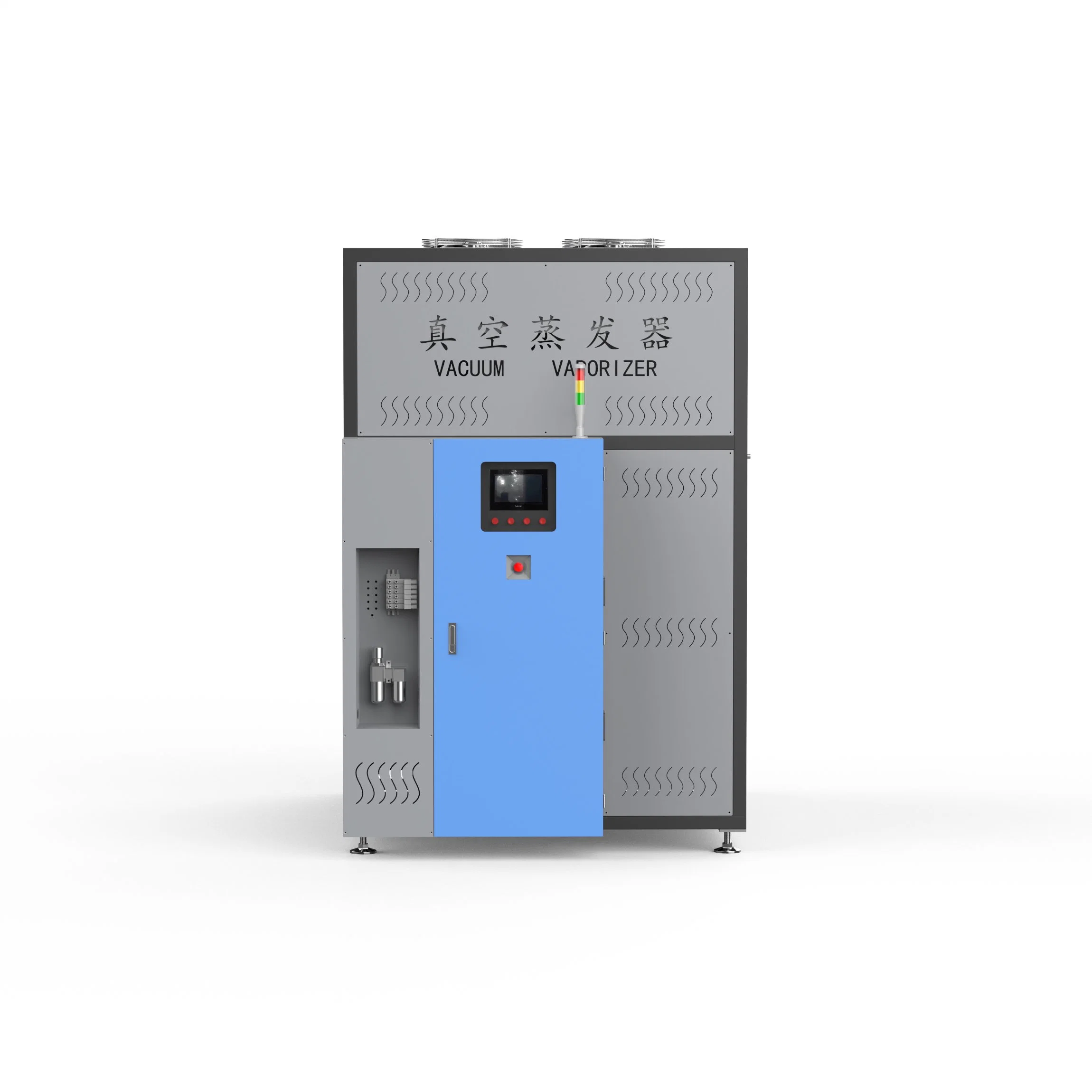
| HVE series heat pump vacuum evaporator | ||
| model:HVE-P2000 | Daily processing capacity:MAX 2000L | Manufacturer: Liheda (Dongguan) environmental protection equipment |
| Liheda (Dongguan) Environmental Protection Equipment Co., Ltd |
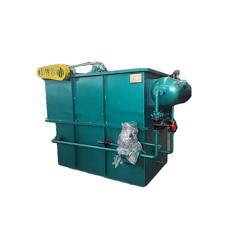
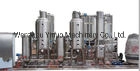
| Sewage Treatment Equipment Based on the Combination of Heat Pump Technology and Vacuum Technology -- Heat Pump Low Temperature Evaporator |
| 1st Floor, Building 6, Songyuan Innovation Technology City, Junda West Road, Dongkeng Town, Dongguan City, Guangdong Province Wang Dewei 13829249131 |
| Processing capacity of water-based liquid: | 2000L/24h |
| Distillation chamber material (sewage contact): | SUS304(Available in 316 2205 2507) |
| Cooling chamber material (distillate contact): | SUS304 |
| Input power voltage: | 380V 50/60HZ Three phase four wire five wire system (grounding wire) 5.8KW |
| Input compressed air: | Dry and clean compressed air above 5KG |
| Sheet metal construction: | Carbon steel powder spraying |
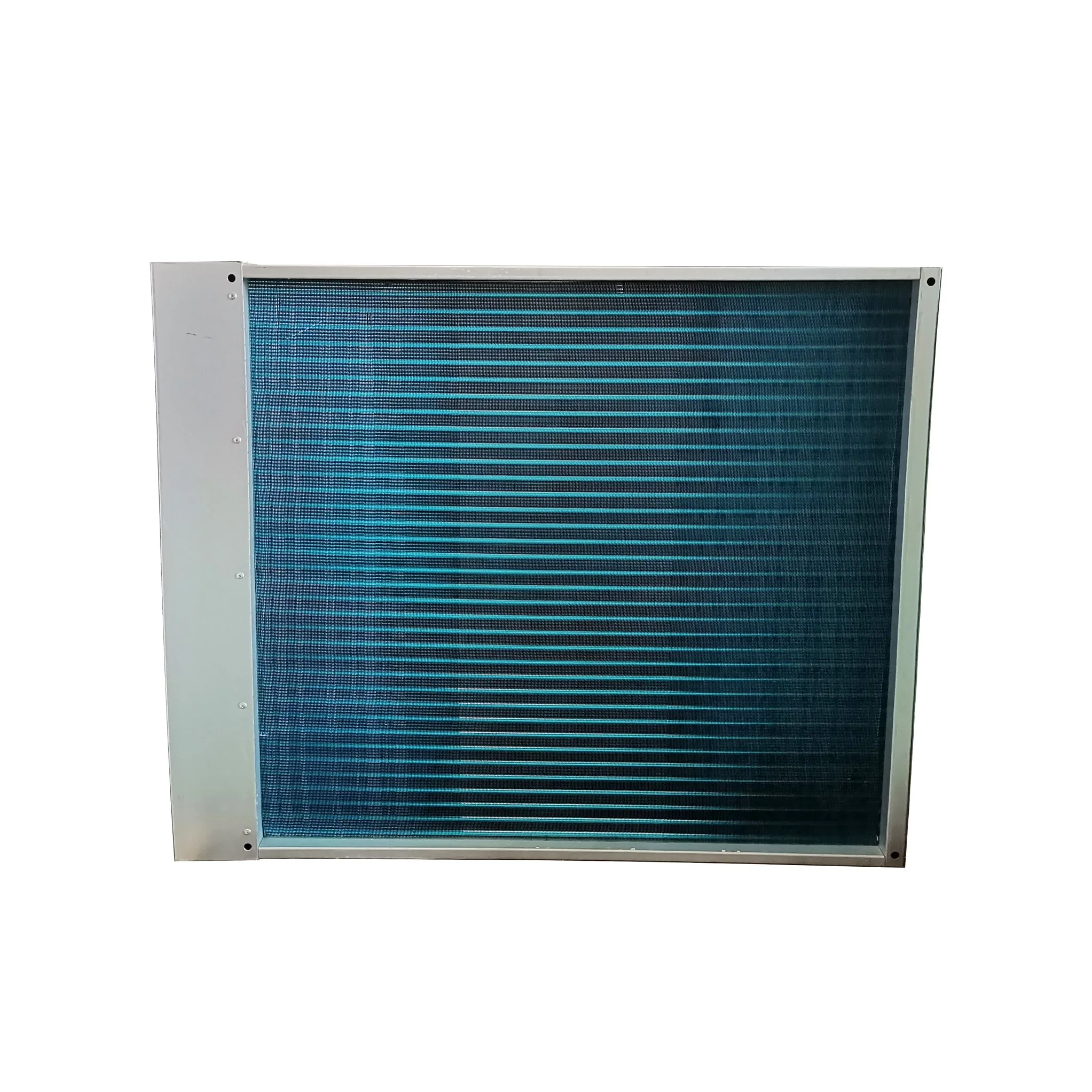
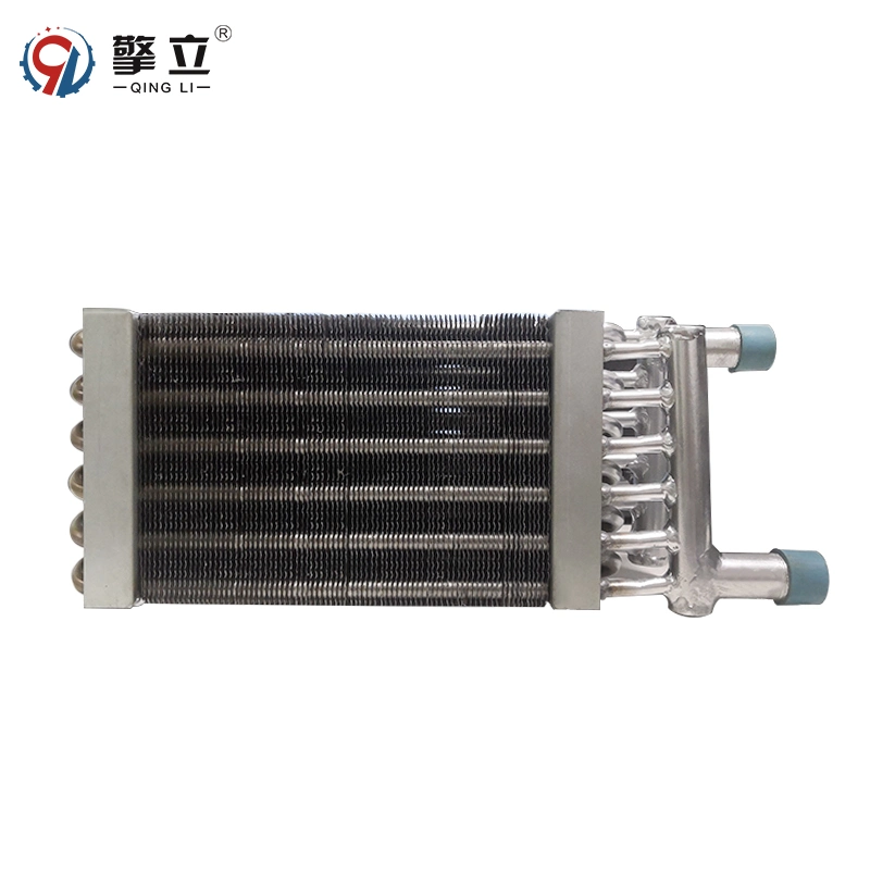
| Heating heat exchanger: | SUS316coil |
| Evaporation type: | Heat pump low-temperature evaporation |
| Evaporation conditions: | -0.92KPA-0.097KPA temperature25-40ºC |
| Evaporation temperature: | 25-40ºC |
| Steam separator: | SUS304Demister |
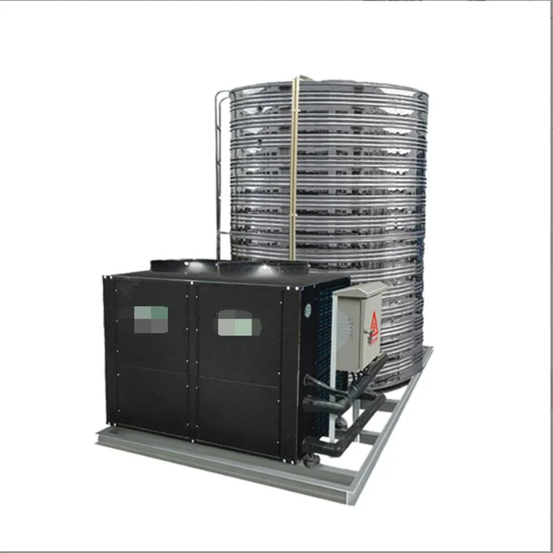
| Heating and cooling technology: | Heat pump circuit |
| Heat pump compressor: | vortex |
| cryogen: | R22 |
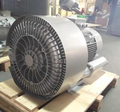
| Vacuum system: | Liquid ejector |
| Operation control: | PLC and HMI intelligent control and 4G remote monitoring |
| Noise: | 68dB (A) measured at 1M from the mechanical surface and 1.6M from the ground |
| power supply | unit | 380V 50/HZ |
| Maximum output of evaporation effluent | L/24h | 1000±10% |
| Absorbed power | KW | 4.25±10% |
| Heat generated by radiator | KW | 4.25±10% |
| Air flow around radiator | Good ventilation | Heat dissipation |
| Temperature at saturated evaporation | Sewage: 37 ºC± 10% Steam: 36 ºC± 10% Distillate temperature: 28 ºC± 10% | |
| Serial No | description | configuration | remarks |
| 1 | Foam inhibitor liquid shortage warning | Standard configuration | |
| 2 | Original liquid barrel | Optional | Standard configuration of suction reminder |
| 3 | Concentrate barrel | Optional | Optional concentration tank full reminder |
| 4 | Distillate barrel | Optional | Optional distillate full warning |
| type | size(MM) | weight(KG) |
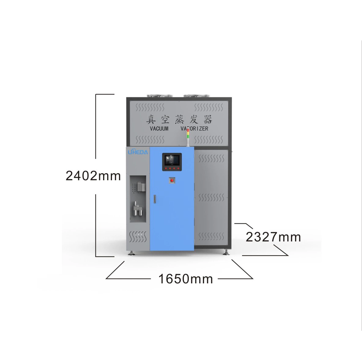
| Unpacked | 2500*1200*2340 | 1345 |
| Condition Type | Working conditions |
| 10-40ºC | Normal |
| 0ºC<temperature<10ºC | It is allowed to start. Precautions: prevent icing |
| >40ºC | Get in touch with Liheda; |
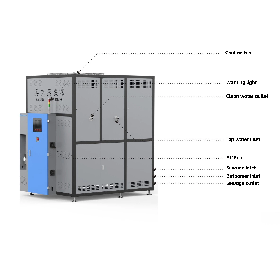
| Serial No | description | type | caliber | requirement |
| 1 | Liquid inlet to be treated | Reserved internal teeth | 1 inch internal tooth | |
| 2 | Concentrate discharge outlet | Reserved internal teeth | 1 inch internal tooth | |
| 3 | Defoamer inlet | Reserved air pipe orifice | 6 cm straight plug | |
| 4 | Distillate outlet | Reserved internal teeth | 6 internal teeth | |
| 5 | Tap water inlet | Reserved internal teeth | 1 inch internal tooth |
| Type | requirement | condition | size | characteristic |
| compressed air | Clean and dry | Above 4BAR | 8 cm air pipe and connector | |
| electric energy | 380V 50/60HZ | 3-phase 5-wire system | Power: 15.8KW | Cable line 16 square meters |