
 Complaint

| Product details | |
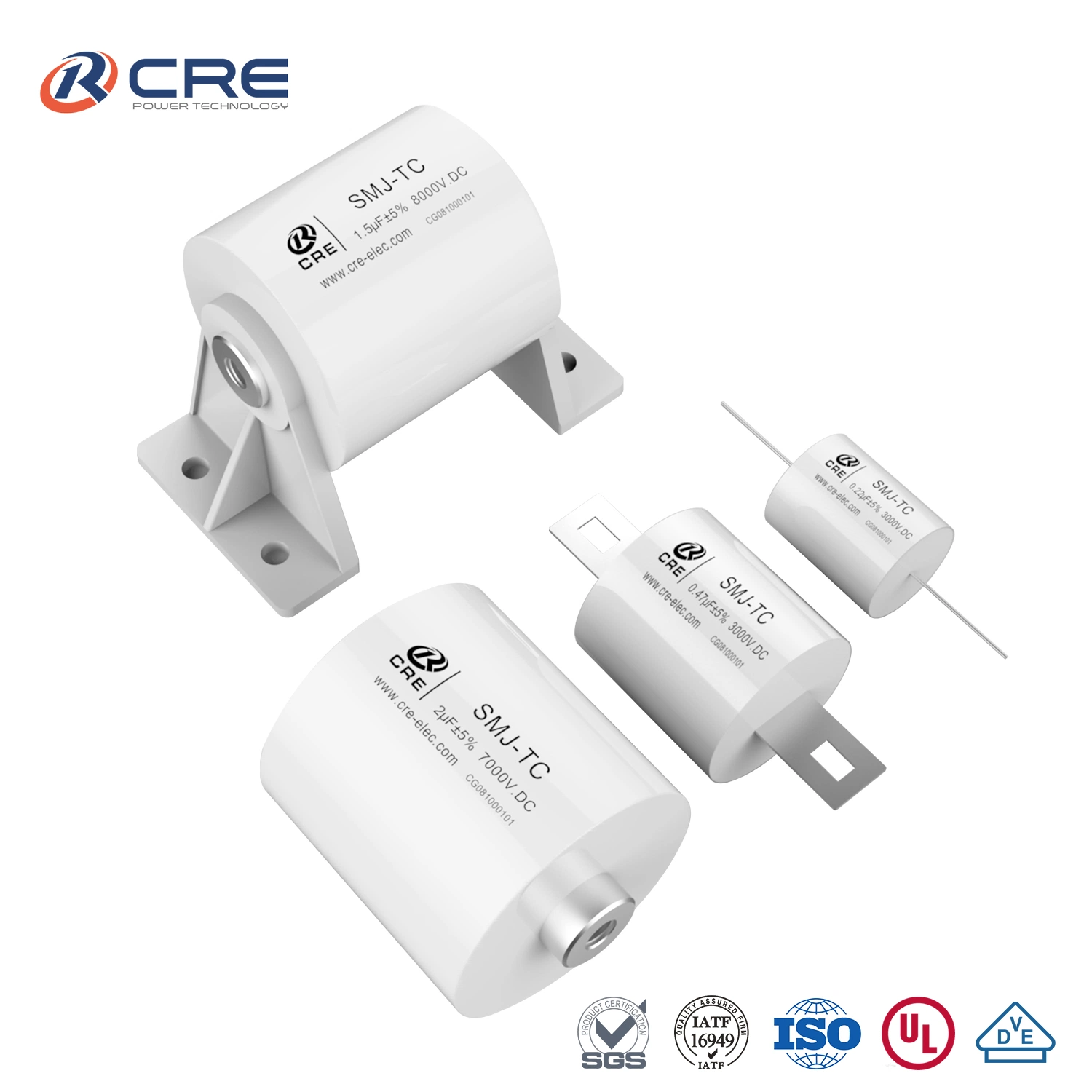
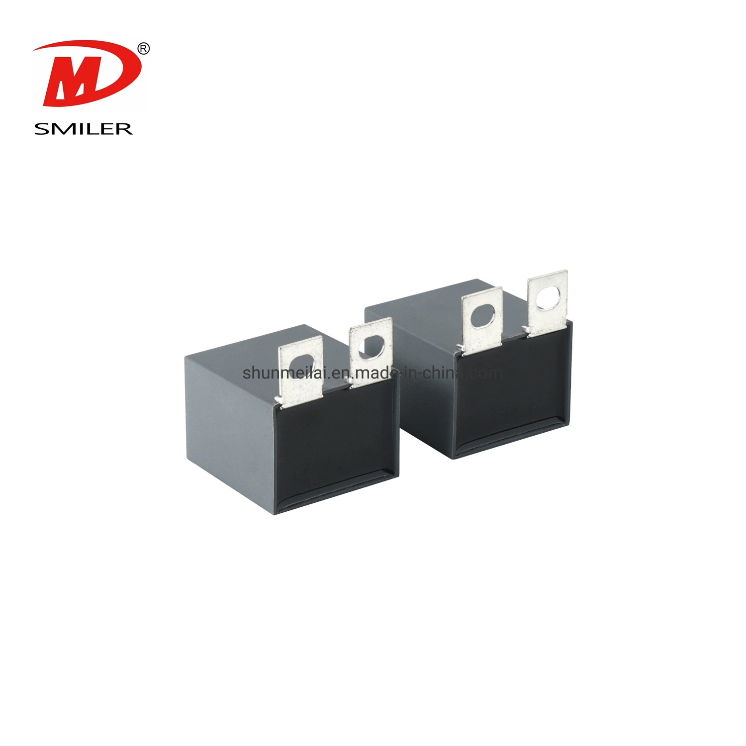
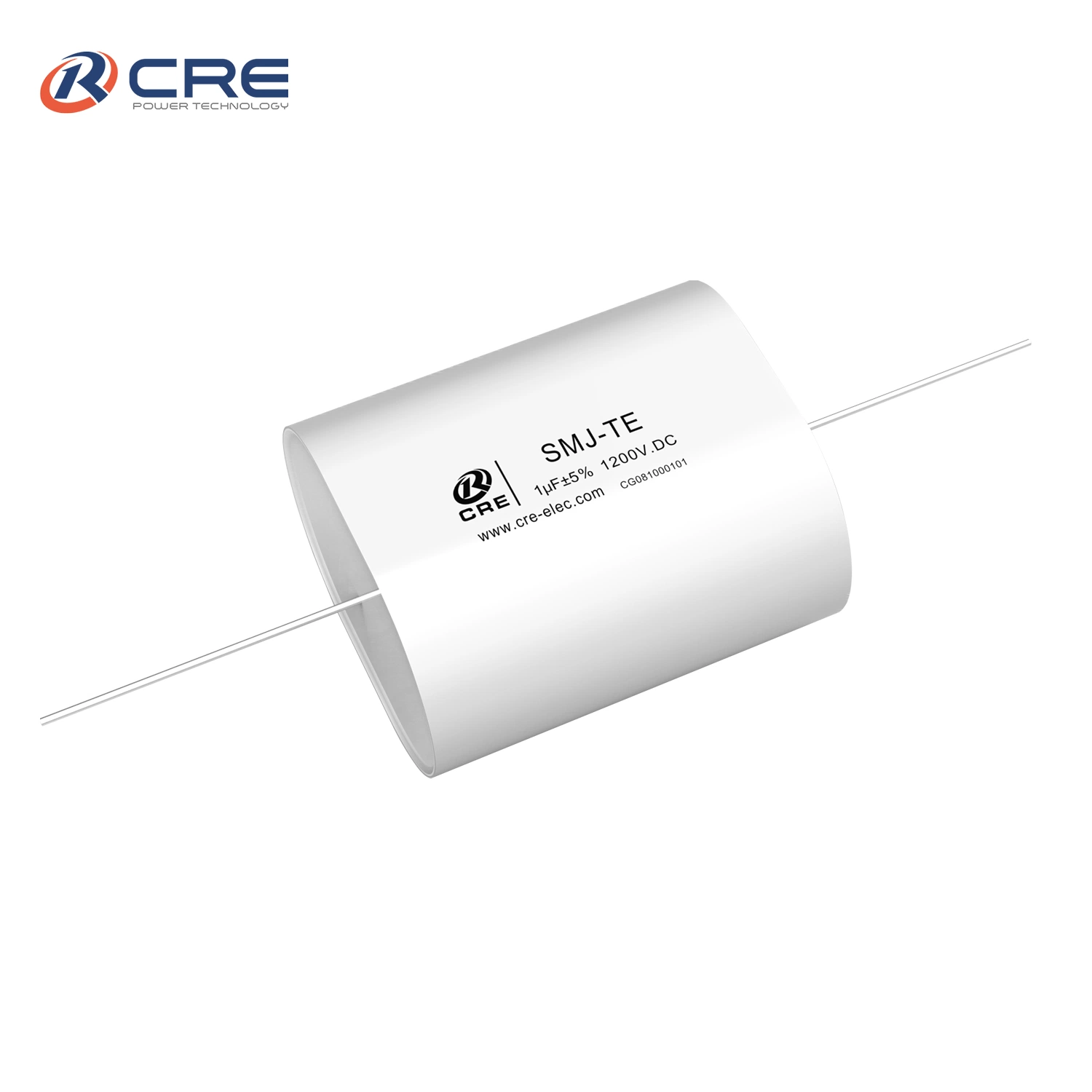
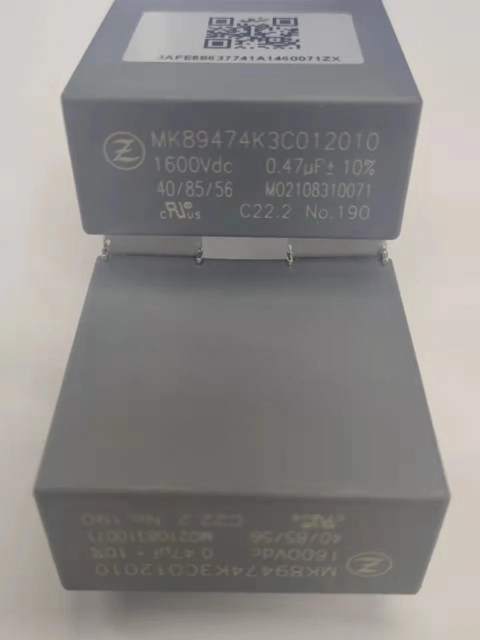
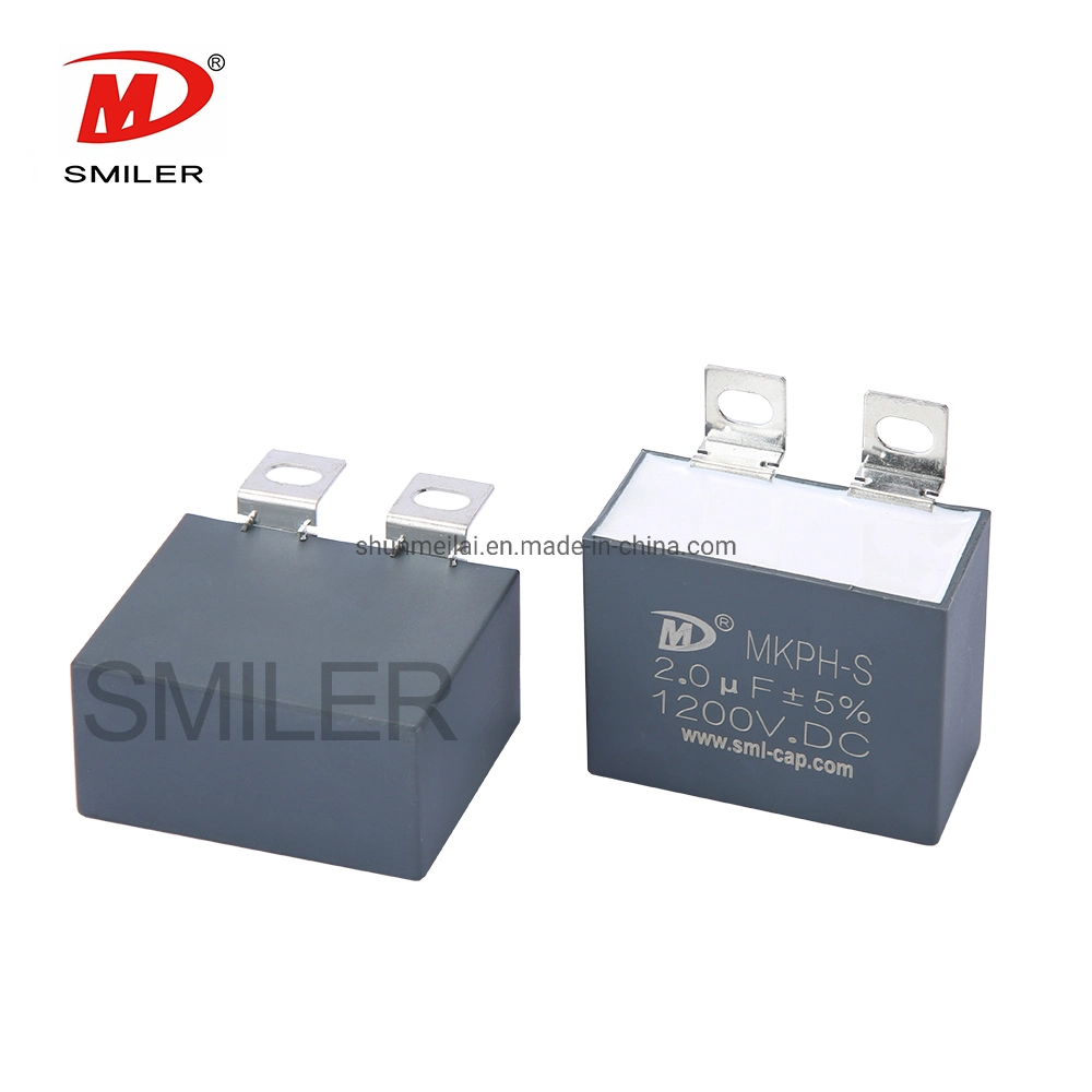
| Product name | IGBT Snubber capacitor |
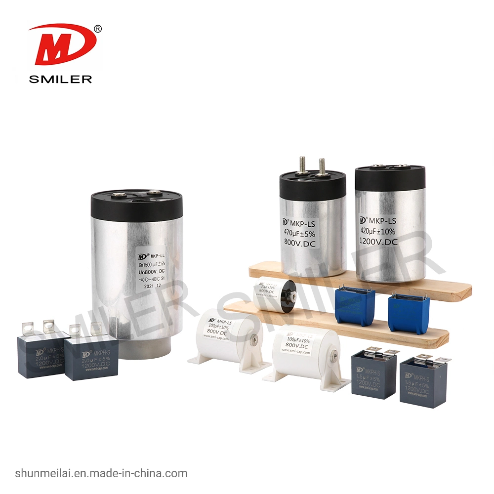
| Type | High Voltage Capacitor |
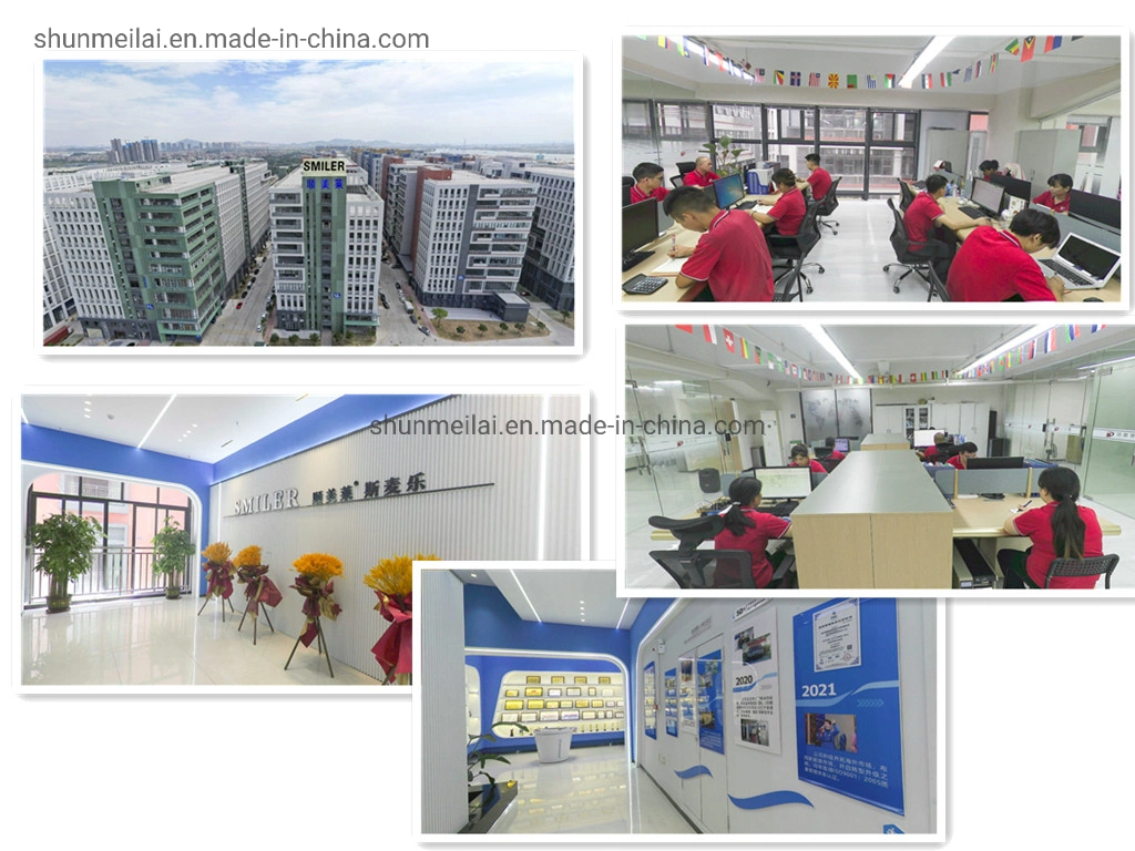
| Place of Origin | Guangdong, China |
| Brand Name | SMILER |
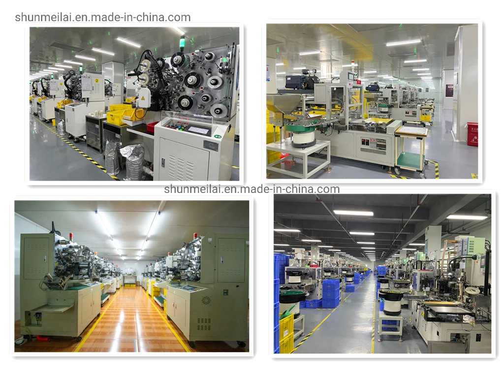
| Supplier Type | Original manufacturer, ODM |
| Capacitance | 2.0UF |
| Media Available | Datasheet, Photo |
| Tolerance | 5% |
| Package Type | Through Hole |
| Rated Voltage | 1200VDC |
| Operating Temperature | -40°c ~ + 105°c |
| Voltage - Rated | 1200VDC |
| ESR (Equivalent Series Resistance) | ≤2mΩ |
| Voltage - Breakdown | 700VDC~3000VDC |
| Capacitance Range | ±5%(J) ± 10%(K) |
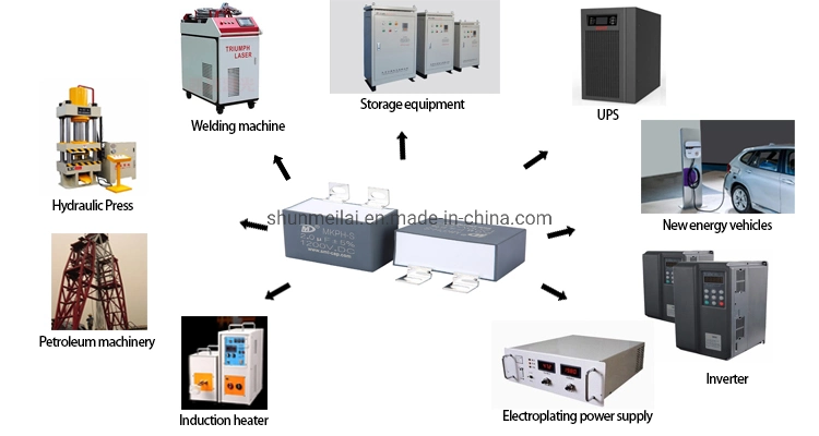
| Applications | Power electric equipment absorption protection |
Capacitor selection and precautions
(1) In the circuit, the actual voltage to be endured by the capacitor cannot exceed its withstand voltage value.
(2) In the filter circuit, the withstand voltage value of the capacitor should not be less than 1.42 times the effective value of the AC voltage. (3) When using electrolytic capacitors and other polar capacitors, be careful not to reverse the positive and negative poles. (4) For the capacitor withstand voltage of the linear power supply, it is generally considered to reserve 40%.
(1) Larger capacitors should be selected for filter capacitors, generally hundreds to thousands of microfarads.
(2) In order to achieve a better filtering effect, capacitors with one large and one small with a difference of at least two orders of magnitude in capacity can be used.
(3) When there is no corresponding capacity in the nominal series, the method of parallel or series capacitors can be used to obtain.
(4) Under normal circumstances, if the fixed value capacitor is damaged, it should be replaced with a capacitor of the same value and withstand voltage.
(5) The general circuit allows to replace the small withstand voltage capacitor with a large withstand voltage capacitor of the same capacity, but not vice versa.
6) Non-polar capacitors cannot be replaced by polar electrolytic capacitors, nor polar capacitors can be replaced by non-polar capacitors.
(7) The coupling capacitor of the audio circuit is generally 0.1~lpF.
(1) Electrolytic capacitors should be used in power supply filtering and low-frequency decoupling circuits.
(2) In high-frequency circuits and high-voltage circuits, ceramic capacitors and mica capacitors should be selected.
(3) In the resonant circuit, mica capacitors, ceramic capacitors and organic film capacitors can be selected.
(4) When used for DC isolation, paper capacitors, polyester capacitors, mica capacitors, electrolytic capacitors and ceramic capacitors can be selected.
For capacitors used in oscillation or delay circuits, the allowable deviation should be as small as possible (generally less than 5%), and in other cases the allowable deviation can be slightly larger (generally 10%~20%).
For polar capacitors with larger capacity, a pointer-type multimeter can be used to test whether the performance of charge and discharge is normal, so as to judge the quality of the capacitor.
The basic properties of capacitors are charging and discharging.
(1) Charging
When the capacitor is connected to the power supply (or two points with potential difference), the capacitor will be charged (that is, the two poles of the capacitor will be charged with the same amount of different charges). The plate connected to the high potential point → the other plate → the negative electrode of the power supply (or the low potential point).
When charging, the voltage across the capacitor increases with the progress of charging. When the resistance values of the power supply and the charging circuit are fixed, the two ends of the capacitor increase exponentially, and the charging current decreases exponentially.
(2) Discharge
When the capacitor is connected to the load, the capacitor will discharge, and the discharge direction is: the positively charged plate of the capacitor - the load - the other plate, until the charge on the plate is zero, the discharge is over.
current direction current direction
During discharge, the voltage across the capacitor decreases with the progress of the discharge. When the resistance value of the discharge circuit is fixed, the voltage across the capacitor and the discharge current decrease exponentially.