 Complaint

Project | Performance Parameter | ||
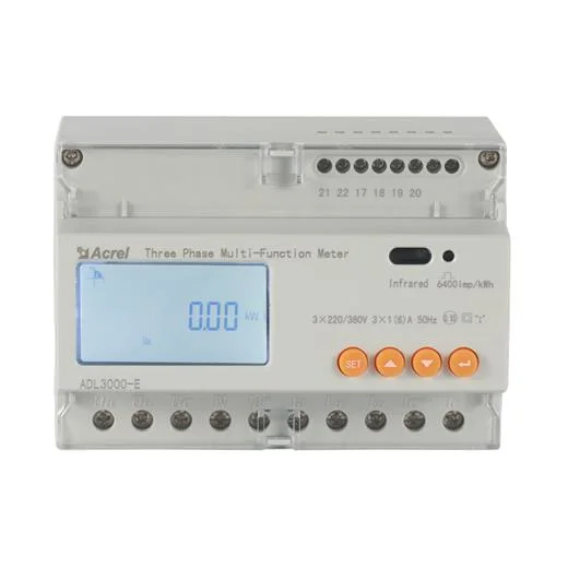
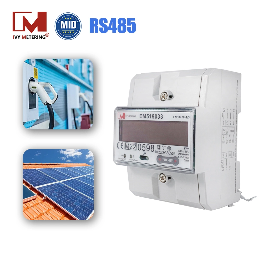
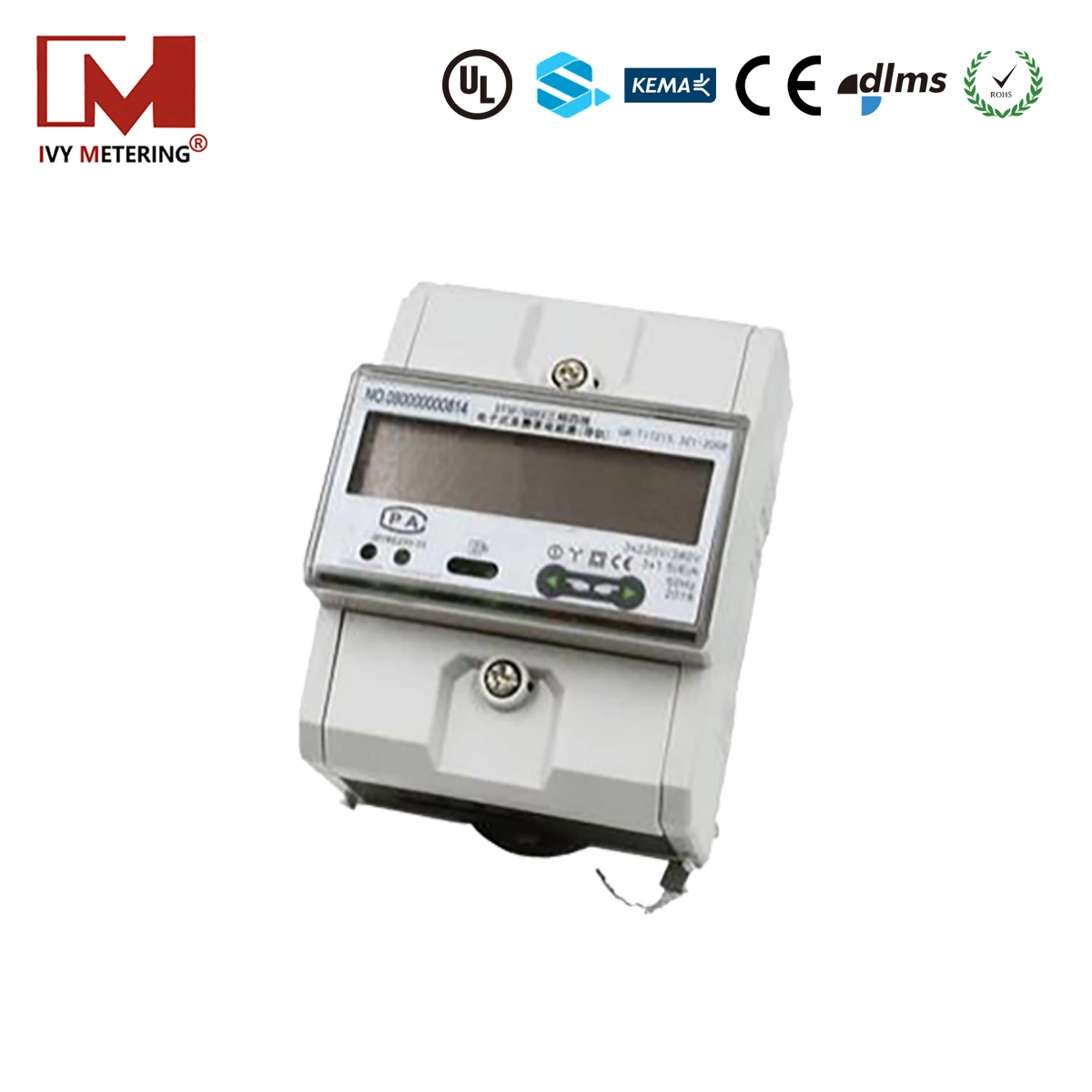
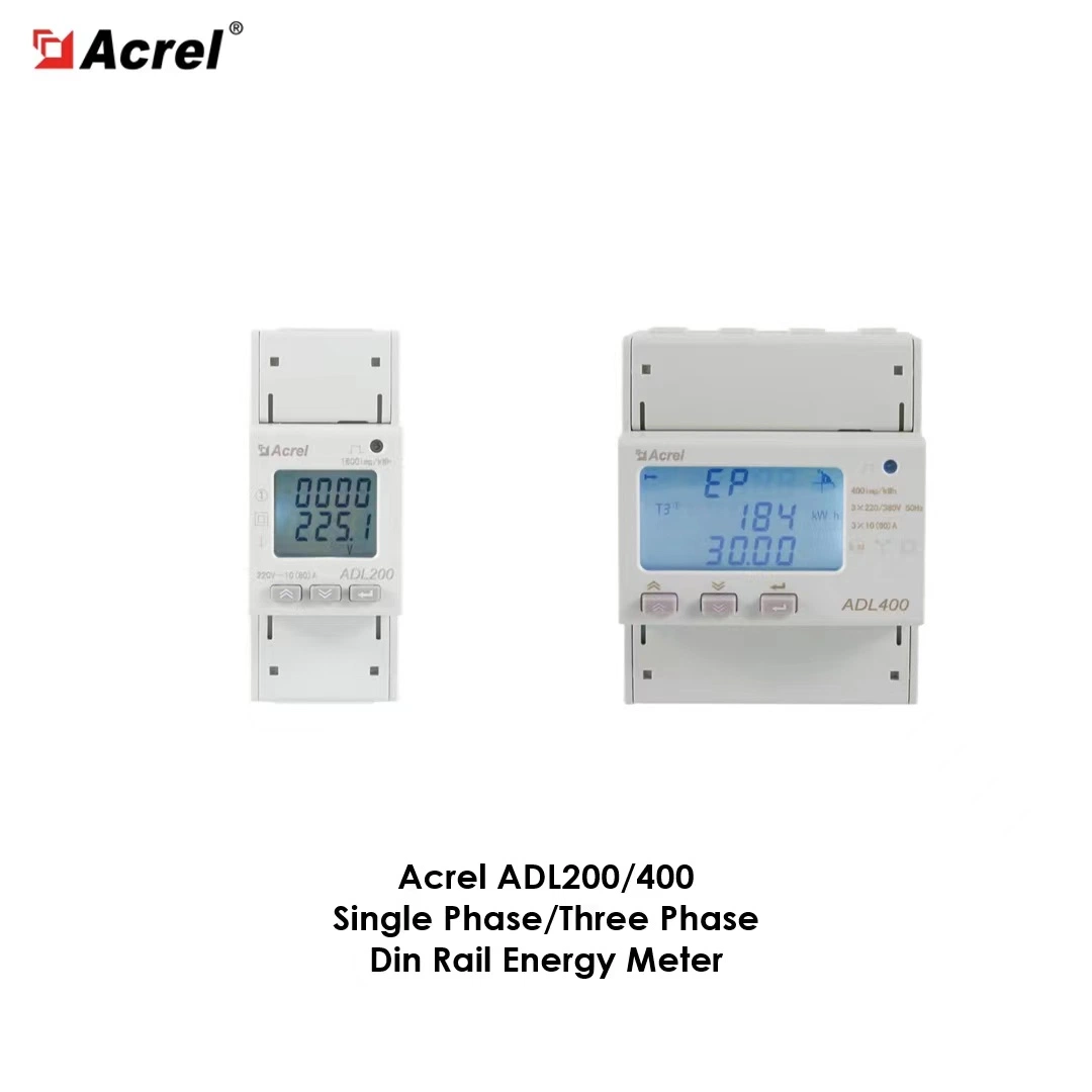
Specification | 3 Phase 3 Wires, 3 Phase 4 Wires | ||
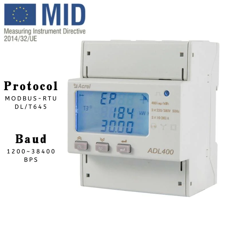
Measurement | Voltage | Reference Voltage | 3*100V, 3*380V, 3*57.7/100V, 3*220/380V |
Consumption | <10VA (Single Phase) | ||
Inpedance | >2MΩ | ||
Accuracy Class | Error ±0.2% | ||
Current | Input Current | 3*1(6)A, 3*10(80)A | |
Consumption | <1VA Single Phase Rated Current | ||
Accuracy Class | Error ±0.2% | ||
Power | Active, Reactive, Apparent, Power, Error ±0.2% | ||
Frequency | 45-65Hz, Error ±0.2% | ||
Metering | Energy | Active Energy (Accuracy Class 0.5) Reactive Energy (Accuracy Class 2) | |
Clock | ≤0.5s/d | ||
Digit Signal | Energy Pulse Output | 1 Active Photocoupler Output | |
Pulse | Width of Pulse | 80±20ms | |
Pulse Constant | 400 imp/kWh, 10000 imp/kWh (Correspond With the Basic Current) | ||
Communication | Interface and Communication Protocol | RS485: Modbus-RTU | |
Range of Communication Address | Modbus-RTU: 1-247 | ||
Environment | Working Temperature | -25ºC-55ºC | |
Relative Humidity | ≤95% (No Condensation) | ||