 Complaint

| NO. | PARAMETER | SPECIFICATION | UNITS | NOTE | ||
| MIN. | TYP. | MAX. | ||||
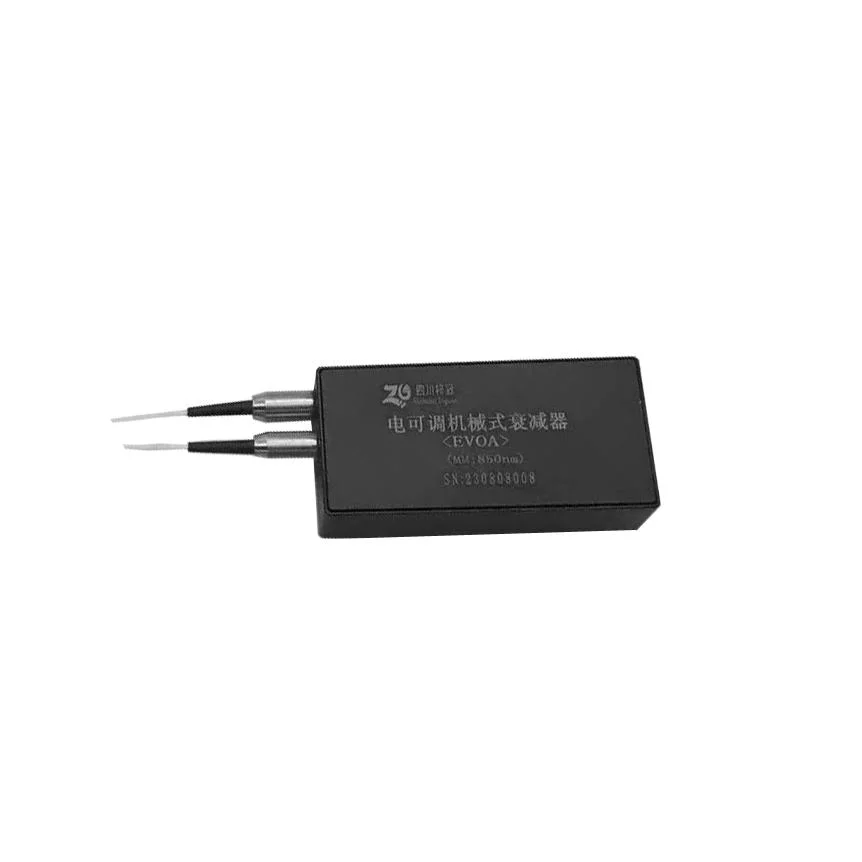
| 2.1.1 | Wavelength range | 800-1100 | nm | |||
| 2.1.2 | Attenuation range | 30 | dB | |||
| 2.1.3 | Respo nse speed @3dB Adjus t Attenuation resolution | 100 | ms | Driven in voltage mode | ||
| 2.1.4 | Attenuation resolution | 0.2 | dB | Full Step | ||
| 2.1.5 | Latching stability | 0.3 | dB | Based on motor power ON to OFF | ||
| 2.1.6 | Insertion loss | 1.0 | dB | With connector, over wavelength rang. | ||
| 2.1·.7 | Attenuation line linearity | 5 | % | 30db@±0.5db | ||
| 2.1.7 | Repeatability | 0.1 | dB | Difference in attenuation on return to a particular attenuation from a random location approaching from the same direction. Note: Attenuation value at a specific voltage/step may vary with age and will vary from unit to unit | ||
| 2.1.8 | Backlash | 0.2 | dB | Difference in attenuation on return to a particular position from a random location. Note: Attenuation value at a specific voltage/step may vary with age and will vary among units | ||
| 2.1.9 | Return loss @Input/output | -25 | dB | With connector | ||
| 2.1.10 | PDL @In/Out | 0.5 | dB | Measured from IN to OUT ports over wavelength range @ whole adjust attenuation range | ||
| 2.1.11 | TDL @In/Out | 0.5 | dB | Measured from IN to OUT ports @ whole adjust attenuation range | ||
| 2.1.12 | PMD@In/Out | 0.15 | ps | |||
| 2.1.13 | Power Handling | 300 | mW | CW | ||
| NO. | PARAMETER | SPECIFICATION | UNITS | NOTE | ||
| MIN. | TYP. | MAX. | ||||
| 2.2.1 | Motor Type | Step Motor,2 Phase | ||||
| 2.2.2 | Motor Current | 150 | 200 | mA | 2 phase on | |
| 2.2.3 | Recommended DC Control Voltage | 3.0 | 3.3 | 3.6 | V | Full stepping and both coils are energized |
| 2.2.4 | Pulse width per step | 1.25 | 2.0 | ms | ||
| 2.2.5 | Motor Resistance | 20 | ||||
| 2.2.6 | Motor Power Dissipation | 2 | W | Over -5~70ºC temperature range | ||
| NO | PARAMETER | SPECIFICATION | UNITS | |
| 3.1 | Operation Temperature | -5 ~ +70 | °C | |
| 3.2 | Operation Humidity | 5 ~ 95 | %RH | |
| 3.3 | Storage Temperature | -40 ~ 85 | °C | |
| 3.4 | Reliability | Accord with the Telcordia GR-910,GR-1209 and GR-1221 requirement. | 1 | |
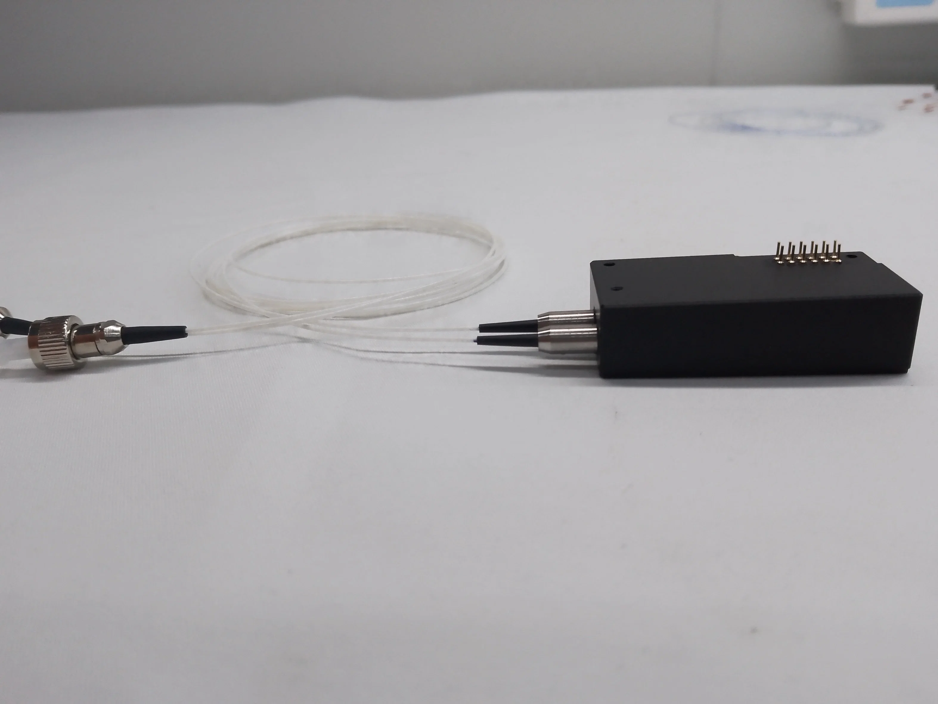
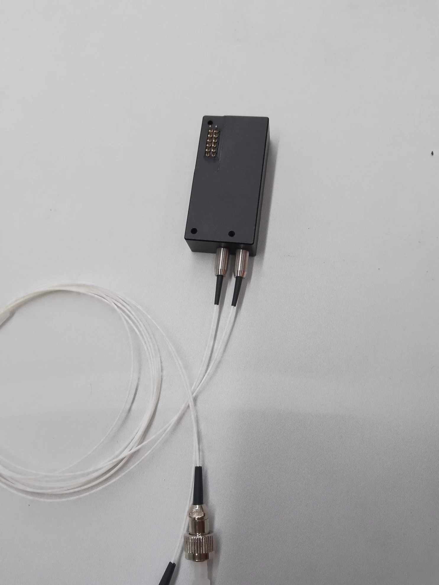
| NO | PIN | DEFINITION | DESCRIPTION | NOTE |
| 5.1 | 1 | Motor Coil A- | ||
| 5.2 | 2 | Motor Coil B | ||
| 5.3 | 3 | Motor Coil B- | ||
| 5.4 | 4 | Motor Coil A | ||
| 5.5 | 5 | Monitor Signal | POT WIPER, Moveable POT contact: voltage pick-off. | |
| 5.6 | 6 | Monitor Supply+ | POT+, Connect to stabilized (reference) positive supply | |
| 5.7 | 7 | Monitor Supply - | POT-, Connect to ground | |
| 5.8 | 8 | Case ground | ||
| 5.9 | 9 | NA | ||
| 5.10 | 10 | NA | ||
| 5.11 | 11 | NA | ||
| 5.12 | 12 | NA |
| NO | PARAMETER | SPECIFICATION | UNIT | NOTE |
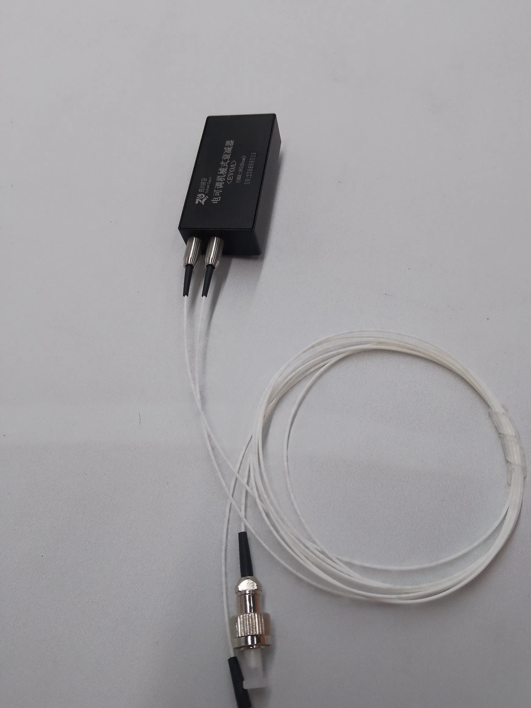
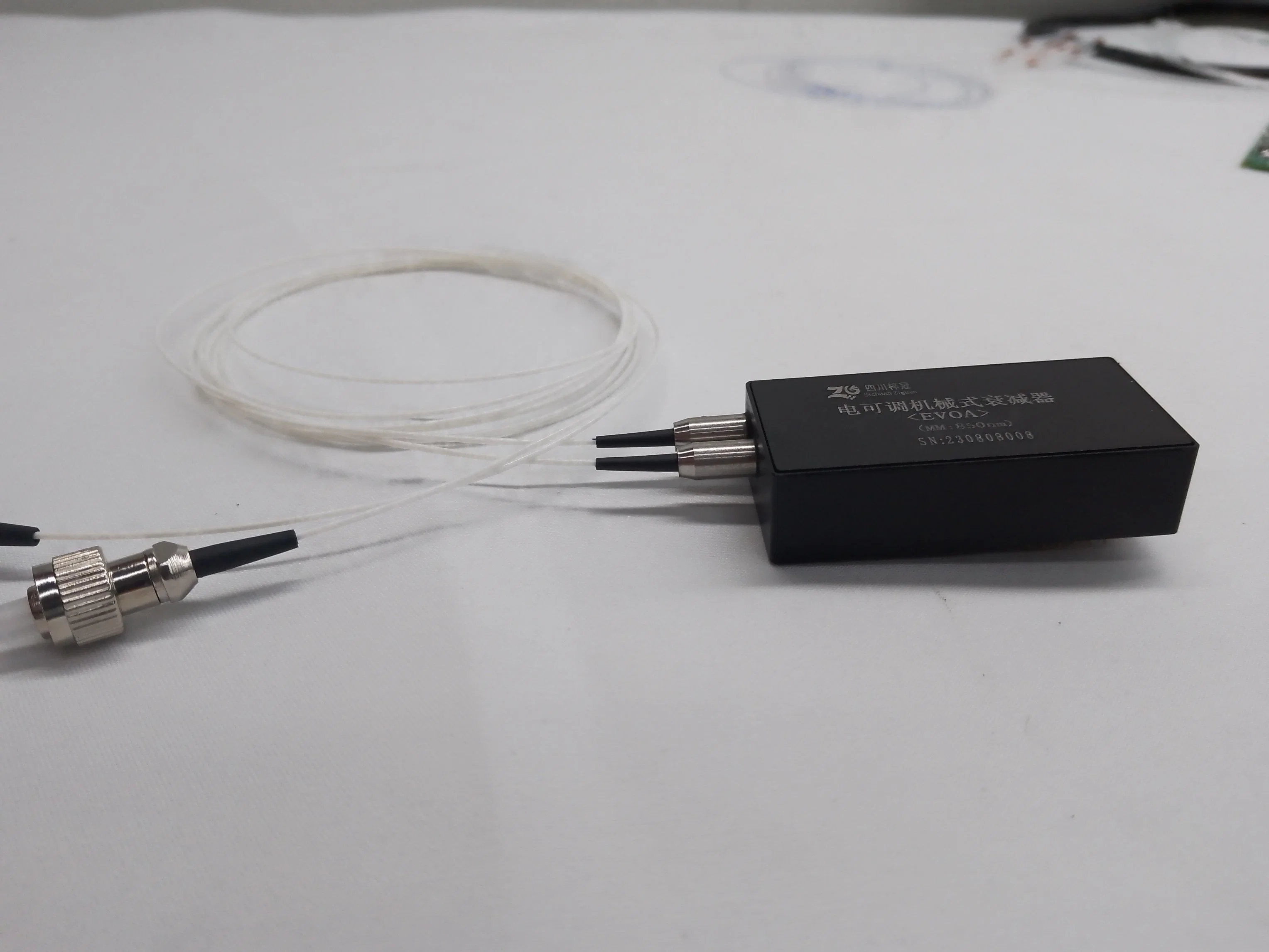
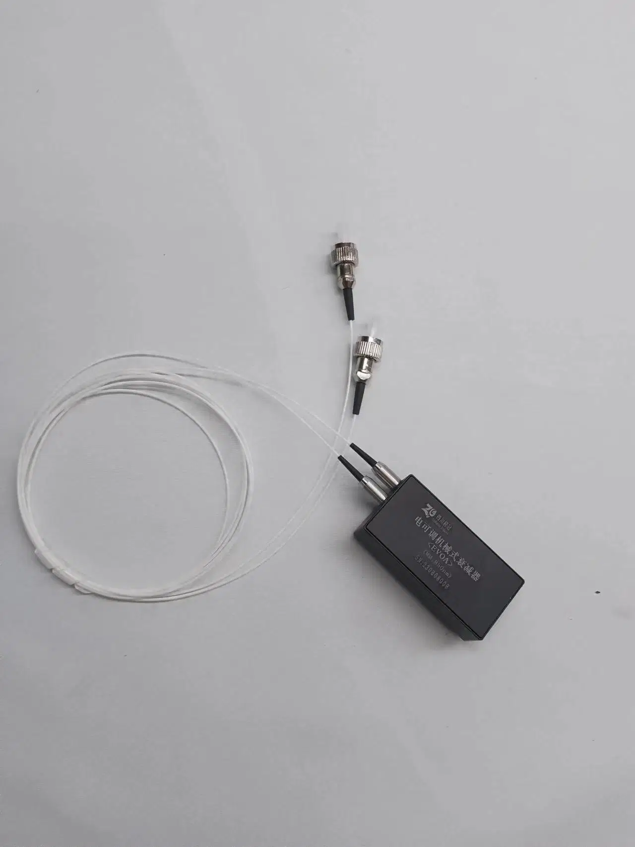
| 8.1 | Pigtail Type(All ports) | 62.5/125um or50/125um Multimode fiber | As customer's requires | |
| 8.2 | Pigtail Length(All ports) | L+/- 0.1 | m | L refers to the fiber length requirement in PN |
| 8.3 | Connector Type(All ports) | As customer's requires |