 Complaint

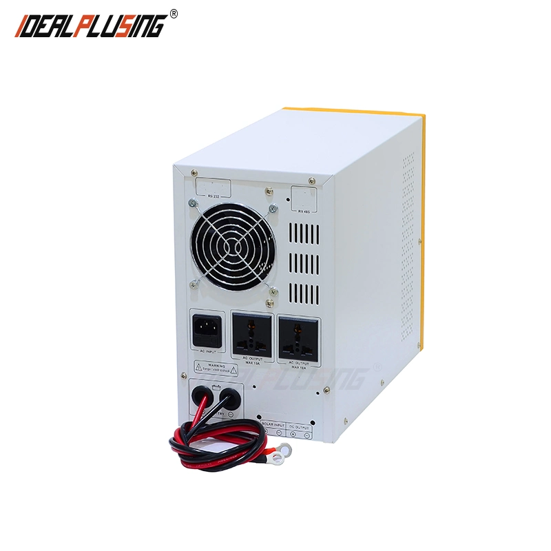
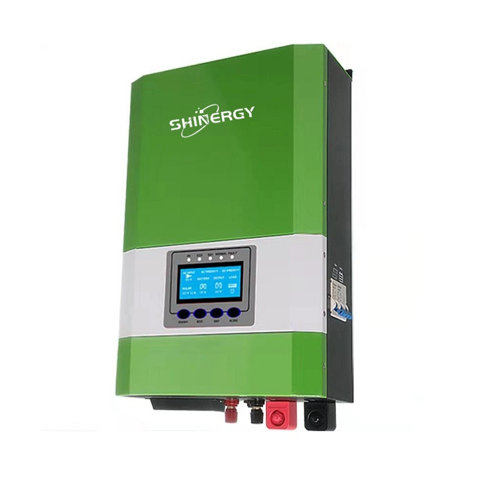
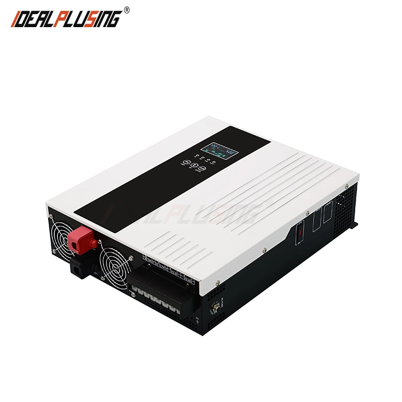
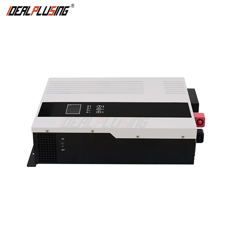
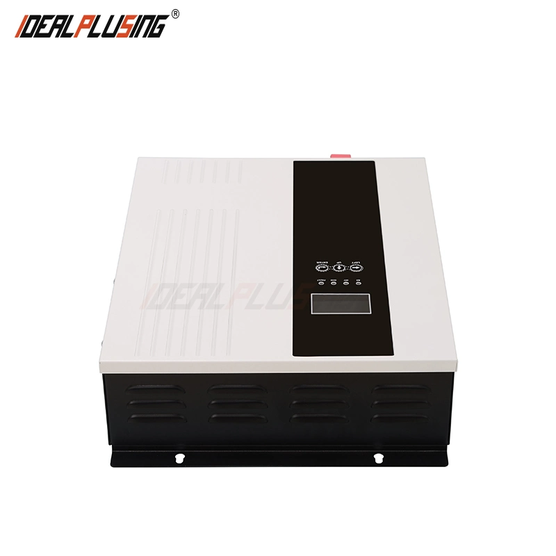
Features:
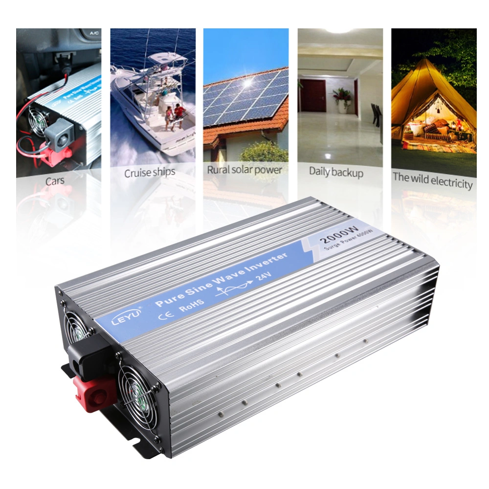
Application Area:
Office and public facilities, home system, network transmission equipment, manufacturing, control system, solar system, oil field, drilling site operation, etc.
Provide stable, reliable, and safe solutions for families, islands, ships, and other small photovoltaic power generation systems
Specification:
| Model: IPS-HP- | 10212 | 15224 | 32224 | 50248 | 72248 | ||||||
| Rated Power | 1000W | 1500W | 3200W | 5000W | 7200W | ||||||
| Peak Power (20ms) | 3000VA | 4500VA | 9600VA | 15KVA | 21.6KVA | ||||||
| Battery Voltage | 12VDC | 24VDC | 24VDC | 48VDC | 48VDC | ||||||
| Product Size (L*W*Hmm) | 434x283x88 | 476x350x118 | 538x388x118 | ||||||||
| Package Size (L*W*Hmm) | 459x347x152 | 502x414x172 | 561x457x172 | ||||||||
| N.W (Kg) | 7 | 7 | 11.5 | 11.8 | 16 | ||||||
| G.W (Kg) | 8 | 8 | 12.5 | 12.8 | 17.5 | ||||||
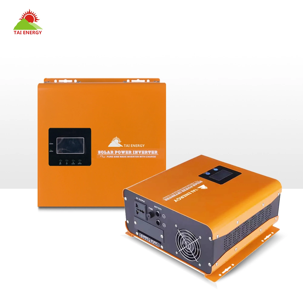
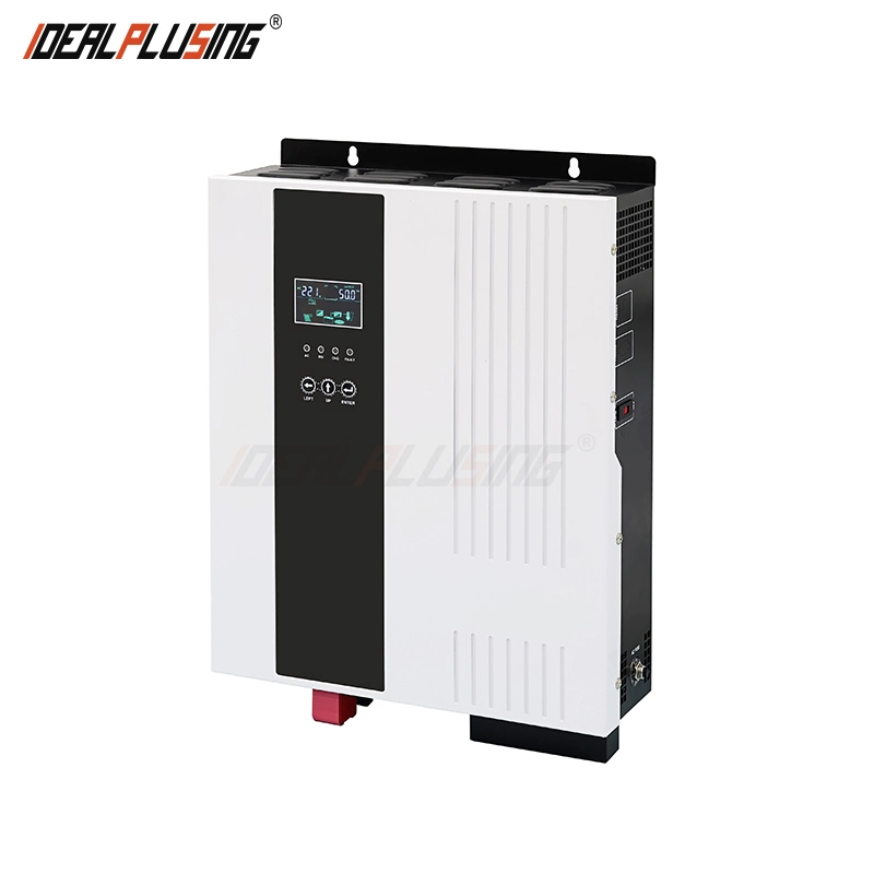
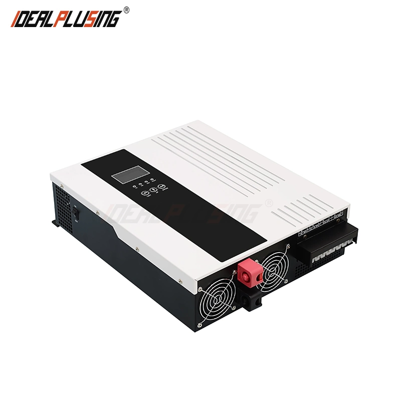
| Installation Method | Wall-Mounted | ||||||||||
| Inside MPPT Solar controller | Charging Mode | MPPT | |||||||||
| Rated PV input voltage | 360VDC | ||||||||||
| MPPT tracking voltage range | 120V-450V | ||||||||||
| Max PV Input Voltage Voc (At the lowest temperature) | 500V | ||||||||||
| PV Array Maximum Power | 200W | 2000W | 4000W | 4000W | 4000W*2 | ||||||
| MPPT tracking channels (input channels) | 1 | 2 | |||||||||
| Inside PWM Solar controller | Charging Mode | PWM | |||||||||
| Charging current | 30A | 60A/120A | |||||||||
| PV Input Voltage Range | 15-44V | 30-44V | 30-44V | 60-88V | |||||||
| Max PV Input Voltage Voc (At the lowest temperature) | 50V | 100V | |||||||||
| PV Array Maximum Power | 420W | 840W | 1680W/3360W | 3360W/6720W | |||||||
| PV input channels | 1 | 1 or 2 | |||||||||
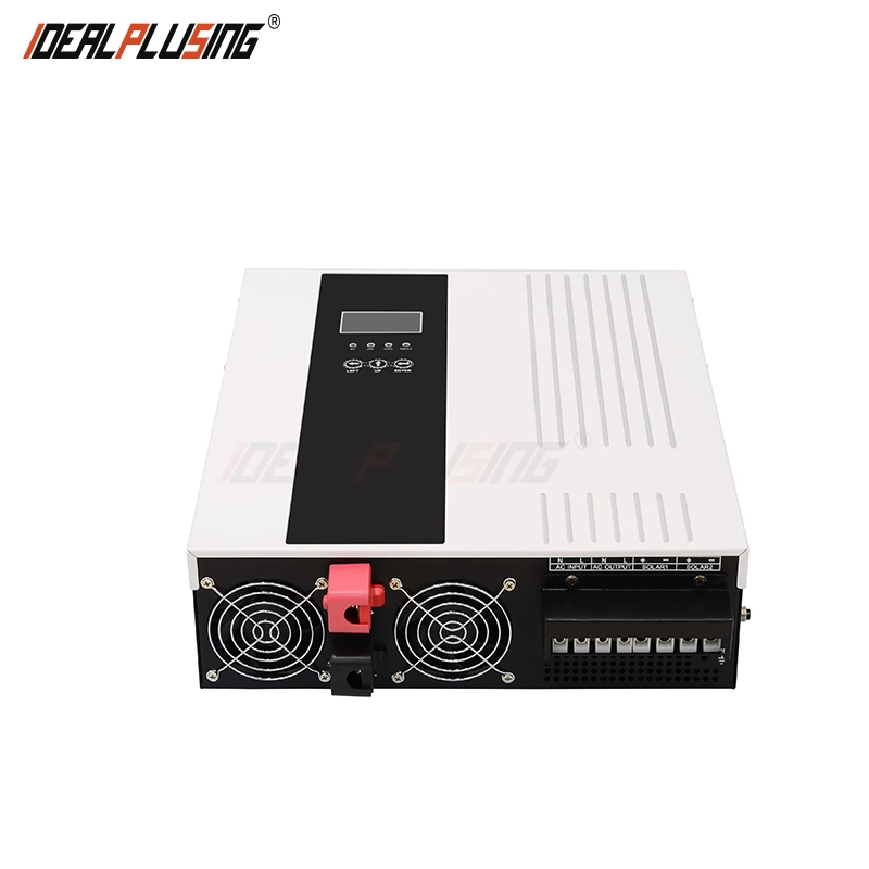
| Input | DC Input Voltage Range | 10.5VDC-15VDC | 21VDC-30VDC | 42VDC-60VDC | |||||||
| Rated AC input voltage | 220VAC /230VAC /240VAC | ||||||||||
| AC Input Voltage Range | 170VAC-280VAC (UPS mode) / 120VAC-280VAC (INVmode) | ||||||||||
| AC Input Frequency Range | 45Hz~55Hz (50Hz), 55Hz~65Hz (60Hz) | ||||||||||
| Output | Output efficiency(Battery/PV Mode) | 94% (Peakvalue) | |||||||||
| Output Voltage(Battery/PV Mode) | 220VAC±2% /230VAC±2% /240VAC±2% | ||||||||||
| Output Frequency(Battery/PV Mode) | 50Hz±0.5or60Hz±0.5 | ||||||||||
| Output Wave(Battery/PV Mode) | Pure Sine Wave | ||||||||||
| Efficiency(AC Mode) | >99% | ||||||||||
| Output Voltage(AC Mode) | Follow input | ||||||||||
| Output Frequency(AC Mode) | Follow input | ||||||||||
| Output waveform distortion Battery/PV Mode) | <3%(Linear load) | ||||||||||
| No load loss(Battery Mode) | <1% rated power | ||||||||||
| No load loss(AC Mode) | <0.5% rated power(charger does not work in AC mode) | ||||||||||
| Battery | Battery Type | VRLA Battery | Charge Voltage :13.8V; Float Voltage:13.7V(Single battery voltage) | ||||||||
| Customize battery | Charging and discharging parameters of different types of batteries can be customized according to user requirements (charging and discharging parameters of different types of batteries can be set through the operation panel) | ||||||||||
| Max AC Charging Current | 60A | 40A | 60A | 60A | 80A | ||||||
| Max PV Charging Current (Built-in MPPT controller model) | 80A | 60A | 100A | 100A | 150A | ||||||
| Maximum charging current (mains + PV) (Built-in MPPT controller model) | 80A | 60A | 100A | 100A | 150A | ||||||
| Maximum charging current (mains + PV) (Built-in PWM controller model) | Mains60A+ PWM controller charging current | Mains40A+ PWM controller charging current | Mains60A+ PWM controller charging current | Mains60A+ PWM controller charging current | Mains80A+ PWM controller charging current | ||||||
| Charging method | Three-stage (constant current, constant voltage, floating | ||||||||||
| Protection | Battery low voltage alarm | Battery undervoltage protection value+0.5V(Single battery voltage) | |||||||||
| Battery low voltage protection | Factory default: 10.5V(Single battery voltage) | ||||||||||
| Battery over voltage alarm | Constant charge voltage+0.8V(Single battery voltage) | ||||||||||
| Battery over voltage protection | Factory default: 17V(Single battery voltage) | ||||||||||
| Battery over voltage recovery voltage | Battery overvoltage protection value-1 V(Single battery voltage) | ||||||||||
| Overload power protection | Automatic protection (battery mode), circuit breaker or insurance (AC mode) | ||||||||||
| Inverter output short circuit protection | Automatic protection (battery mode), circuit breaker or insurance (AC mode) | ||||||||||
| Temperature protection | >90°C(Shut down output) | ||||||||||
| Working Mode | Mains priority/Solar priority/Battery priority(Can be set) | ||||||||||
| TransferTime | <4ms | ||||||||||
| Display | LCD + LED | ||||||||||
| Thermal method | Cooling fan in intelligent control | ||||||||||
| Communication(Optional) | RS485/APP(WIFI monitoring or GPRS monitoring) | ||||||||||
| Environment | Operating temperature | -10°C~40°C | |||||||||
| Storage temperature | -15°C~60°C | ||||||||||
| Noise | <55dB | ||||||||||
| Elevation | 2000m(More than derating) | ||||||||||
| Humidity | 0%~95% (No condensation) | ||||||||||
1. Battery number and capacity should be configured according to the rated voltage of the solar power system or inverter;
2. We offer 3 optional working modes (transfer time≤4ms):
01 Grid priority mode: When the grid and battery are connected to the inverter, the grid will supply power to the loads directly after the voltage is stabilized and charge batteries via an inverter. When the grid is cut off, the battery will automatically continue to supply power via an inverter.
02 Energy saving mode: If the power of the connected AC loads is lower than 5% of the inverter's rated power, there will be no output from the inverter. Only the chip of the inverter is working. The power consumption of the inverter is only 1~6W. The LCD shows the output voltage of 0. If the power of the connected loads is over 5%, within 5S the inverter will automatically convert DC to AC to supply power for the loads. The LCD shows the output voltage.
03 Battery priority mode: When the grid and battery are connected to the inverter, the battery will supply power to the loads first. When battery capacity is not enough, the grid will continue to supply power automatically.