Description
Product Description
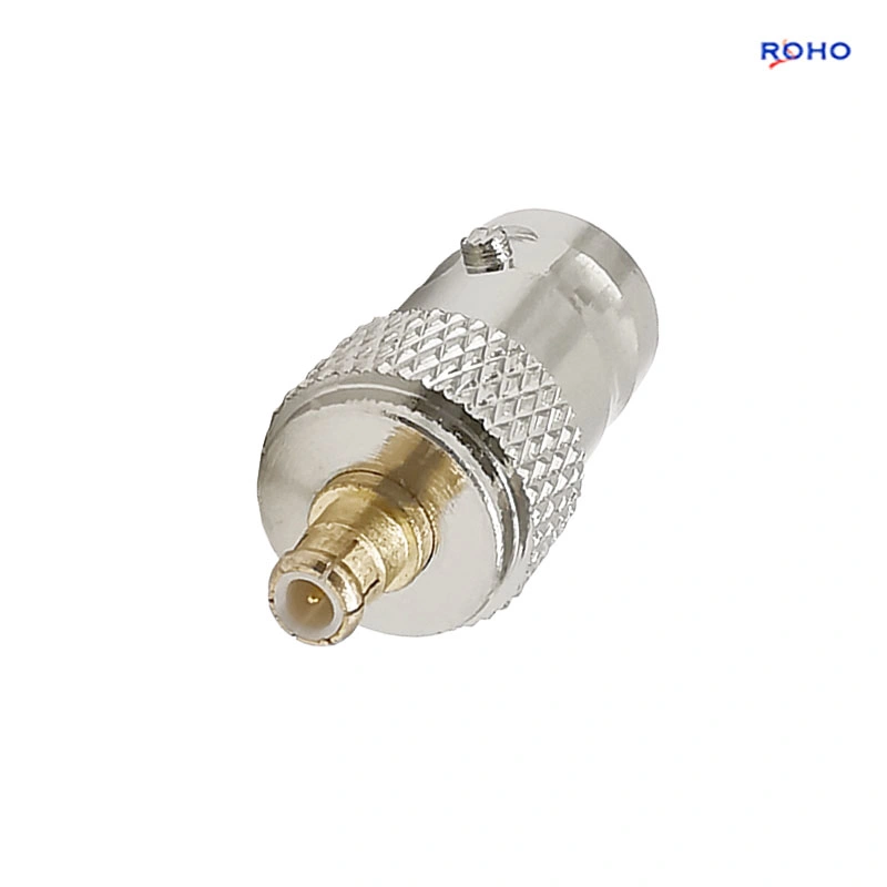
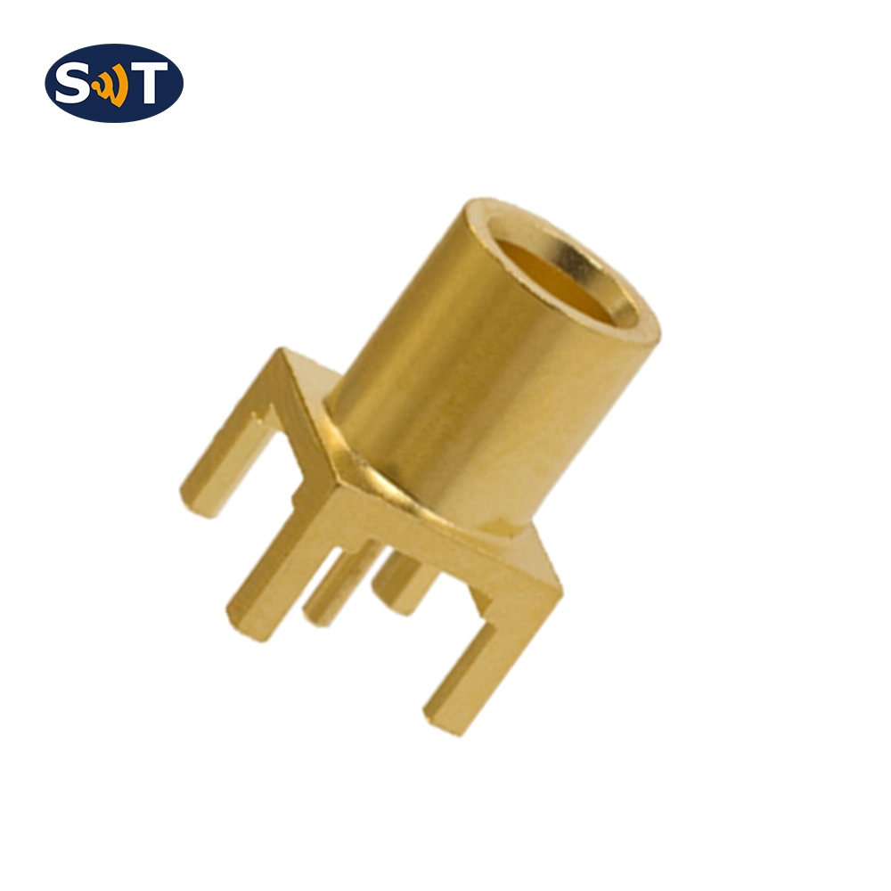
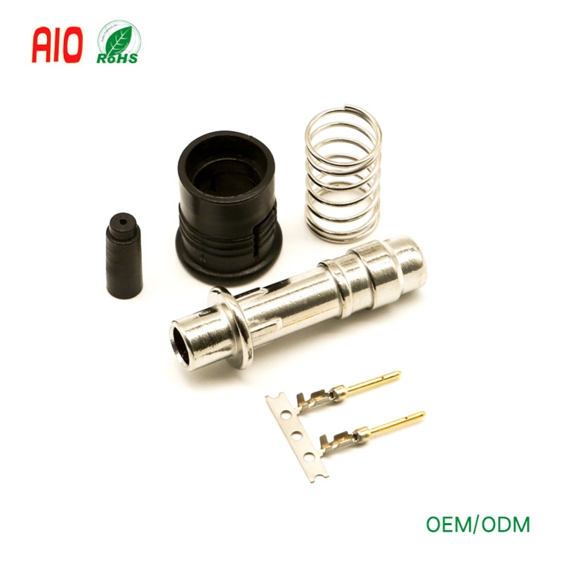
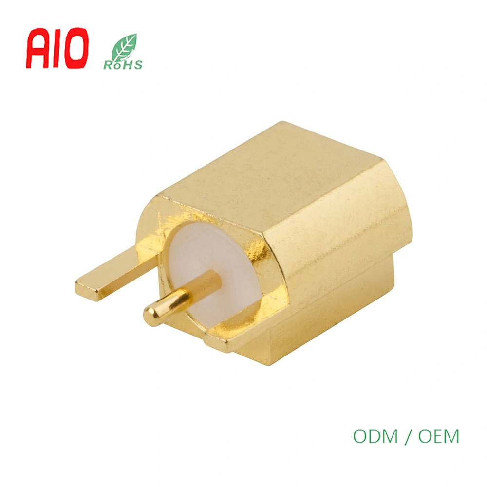
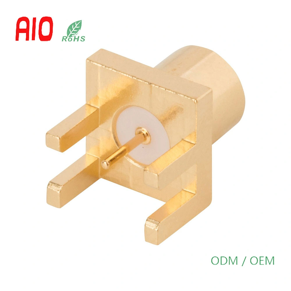
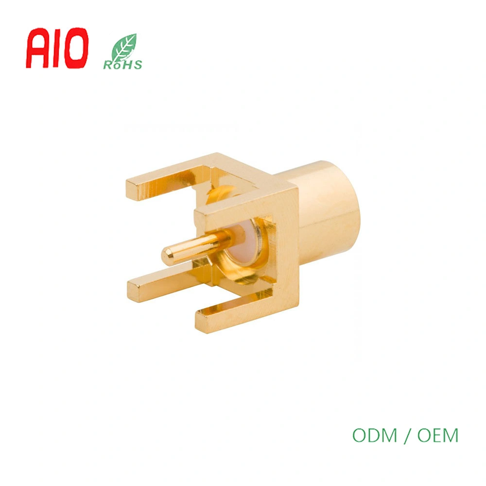
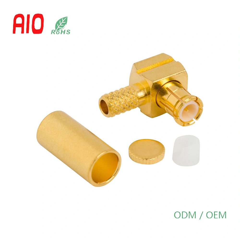
RF Connector MCX Straight PCB Jack End Launch 75 Ohm
Product Life Cycle
Product Life Cycle| Part Status | Active |
|---|
Product Specifications
| Body Finish | Nickel |
|---|
| Body Material | Brass |
|---|
| Cable Type (Terminates to) | Not Applicable |
|---|
| Contact Finish | Gold |
|---|
| Contact Material | Beryllium Copper |
|---|
| Contact Termination | Solder |
|---|
| Coupling Mechanism | Push-on |
|---|
| Frequency (Max GHz) | 6 |
|---|
| Gender | Jack |
|---|
| IP Rating | Not Rated |
|---|
| Impedance (Ohms) | 50 |
|---|
| Insulator Material | PTFE |
|---|
| Isolated | No |
|---|
| Low PIM | No |
|---|
| Mil Qualified | No |
|---|
| Non Magnetic | No |
|---|
| Orientation | Straight |
|---|
| PCB Thickness (Max) | 0.062 Inches (1.57 mm) |
|---|
| Panel Mounting Feature | Not Applicable |
|---|
| Ports | 1 (Single Port) |
|---|
| Termination Style | PCB - End Launch |
|---|
The MCX (Micro Coaxial) series is available with 50 or 75 ohm options, and has broadband capability ranging from DC to 6 GHz. In addition, the MCX series features secure, fast and easy snap-on/ snap-off coupling. MCX connectors were introduced in the 1980s and conform to the European CECC 22220 spec.
This series provides designers with options where weight and physical space are limited. While the MCX uses identical inner contact and insulator dimensions as the SMB, the outer diameter of the plug is .140 inches, which is 30% smaller than the SMB.
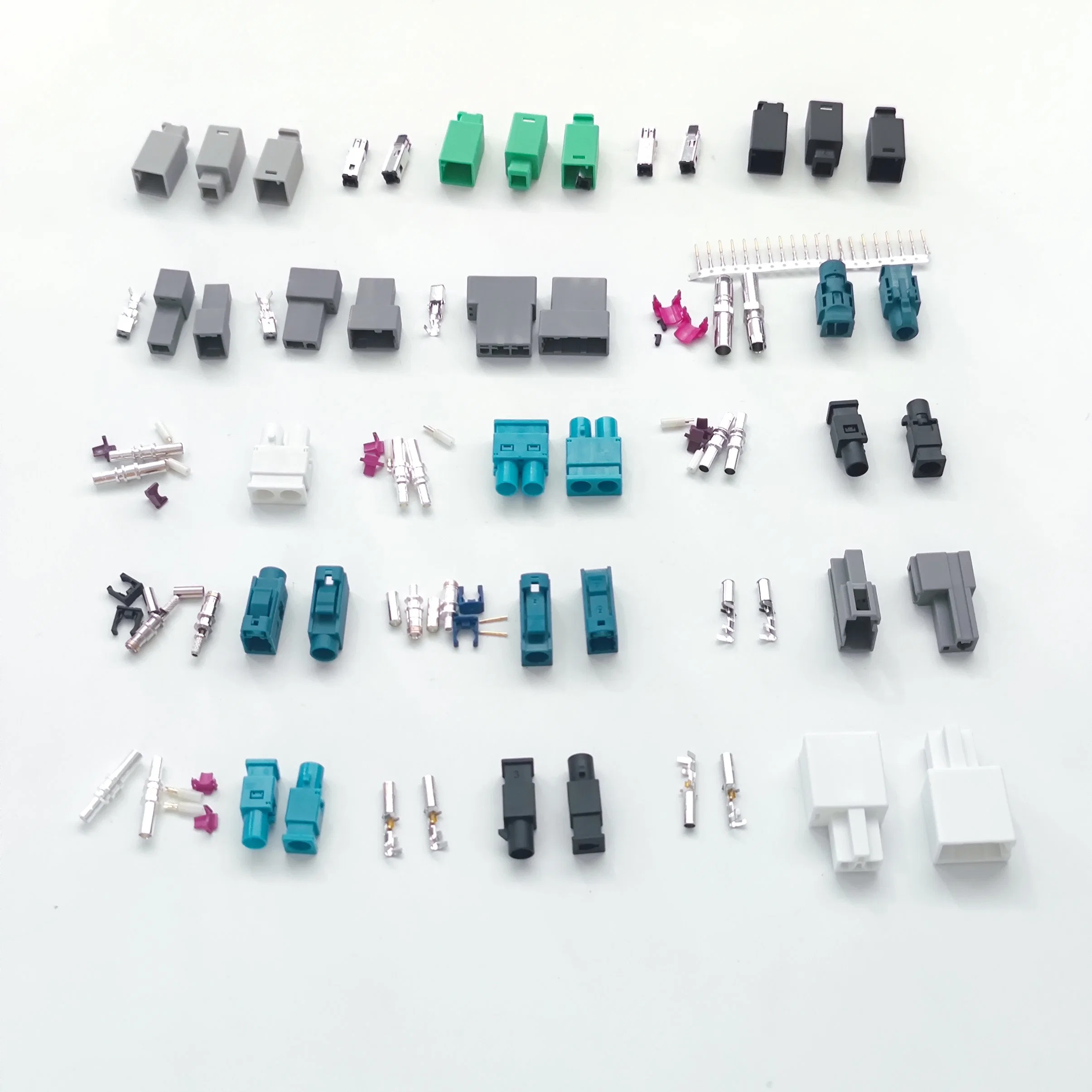
A robust range of connectors are available, including printed circuit board and cable connectors, as well as 12G optimized products.
Features and Benefits- Broadband performance with low reflection DC to 6 GHz
- Quick connect/disconnect snap-on mating reduces installation time
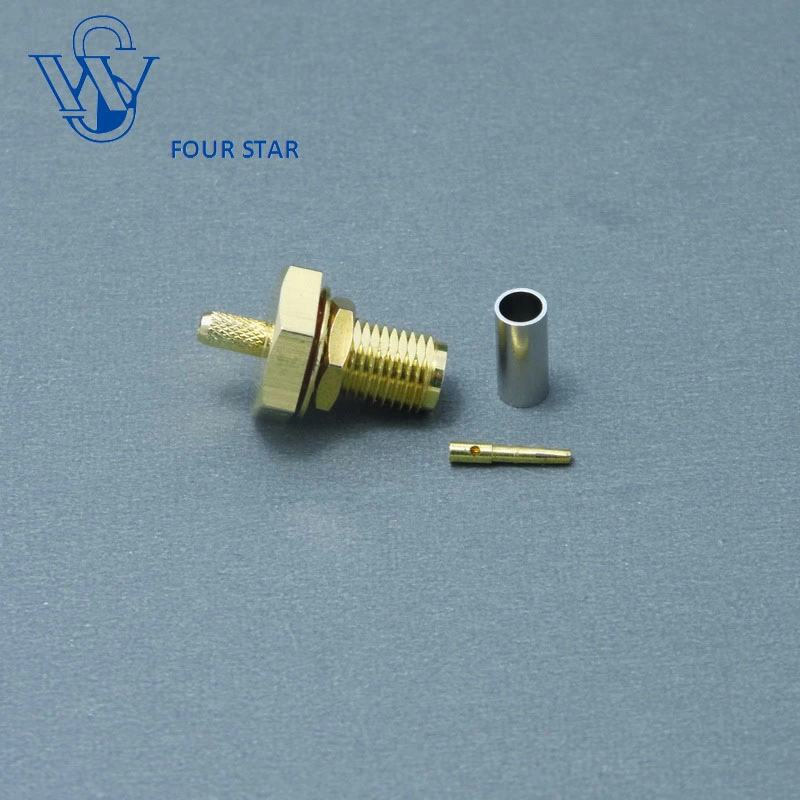
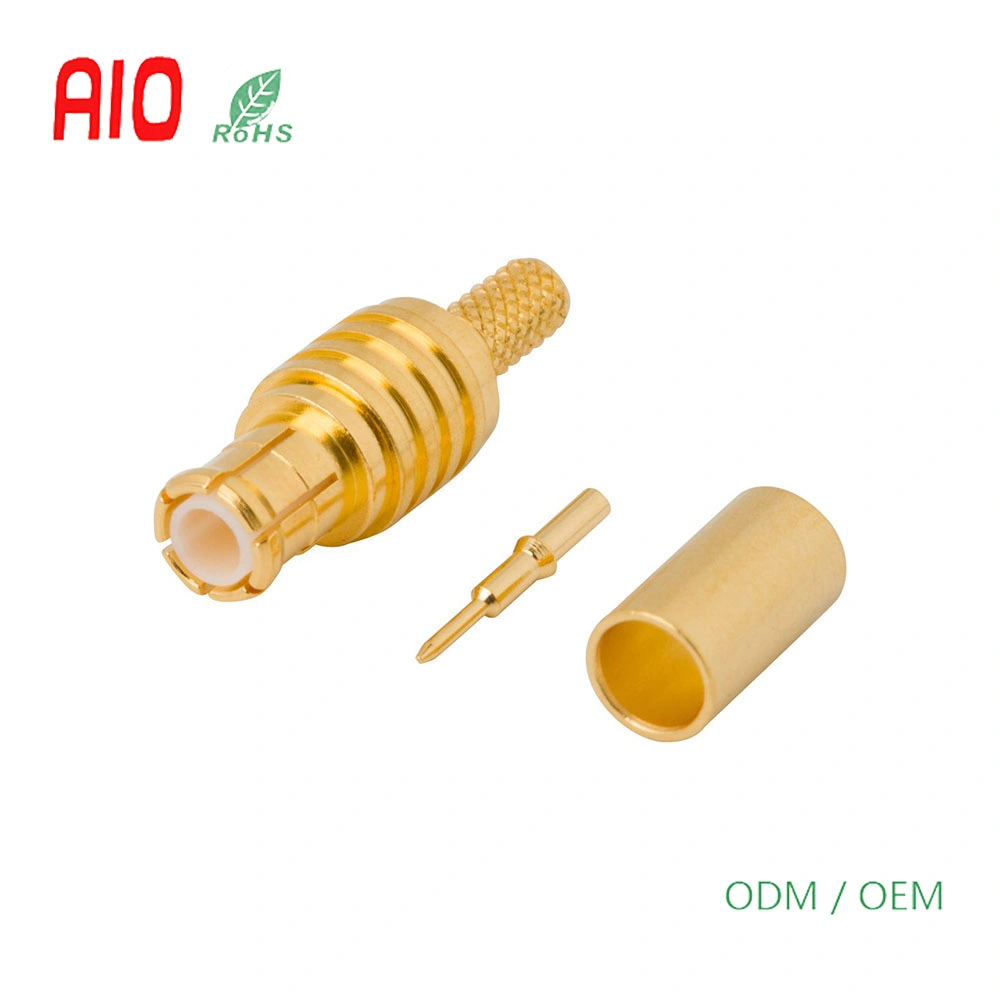
- Accommodates a wide range of miniature RG flexible coaxial cables, including semi-rigid cable providing customers flexibility in their design and manufacturing
- Available for 50 or 75 ohm applications
Applications- WLAN
- Global Positioning System (GPS)
- PC/LAN
- Automotive
- Base Station
- Head End Equipment
- Radios
- Wireless/Network Antenna
- Instrumentation
- Telecommunications
MCX Connectors Specifications
50 Ohm
Electrical
Items| Impedance | 50 Ohm |
| Frequency Range | DC - 6 GHz |
| Voltage Rating | 225 Volts RMS Max Continuous |
| Dielectric Withstanding Voltage | 1000 VRMS Max |
| VSWR (Return Loss) | |
| DC - 6 GHz | 1.3 (-18 dB) Max |
| Insulation Resistance | 10000 M Ohm Min |
| Center Contact Resistance | 5 m Ohm Min |
| Outer Contact Resistance | 1 m Ohm Min |
| RF Leakage | -60 dB Max @ 1 GHz |
| Insertion Loss | 0.10 db Max @ 1 GHz |
| Power Handling | 95 W Max @ 1 GHz @ 25 ºC |
Environmental
Items| Temperature Range | −65°C to +165°C |
| Thermal Shock | MIL-STD-202, Method 107 (Test Condition B), Except high temperatures @ +200°C |
| Corrosion | MIL-STD-202, Method 101 (Test Condition B) - 5% Salt Solution |
| Vibration | MIL-STD-202, Method 204, Snap-On (Test Condition B) |
| Mechanical Shock | MIL-STD-202, Method 213, Snap-On (Test Condition B) |
| Moisture Resistance | MIL-STD-202, Method 106 |
Mechanical
Items| Mating Cycles | 500 Min |
| Coupling Mechanism | Push-On |
| Interface Specification | CECC 22220 |
| Engagement Force | 20 N Max |
| Disengagement Force | 10 N Min |
75 Ohm
Electrical
Items| Impedance | 75 Ohm |
| Frequency Range | DC - 6 GHz (0 - 18 GHz on 12G Products) |
| Voltage Rating | 170 Volts RMS Max Continuous |
| Dielectric Withstanding Voltage | 500 VRMS Max |
| VSWR (Return Loss) | |
| 12G Products: DC - 6 GHz | 1.22 (-20 dB) Max |
| 12G Products: 6 - 12 GHz | 1.43 (-15 dB) Max |
| Insulation Resistance | 10000 M Ohm Min |
| Center Contact Resistance | 5 m Ohm Min |
| Outer Contact Resistance | 2.5 m Ohm Min |
| RF Leakage | -60 dB Max @ 1 GHz |
| Insertion Loss | 0.10 dB Max @ 1 GHz |
| Power Handling | 95 W Max @ 1 GHz @ 25 ºC |
Environmental
Items| Temperature Range | −65°C to +165°C |
| Thermal Shock | MIL-STD-202, Method 107 (Test Condition B), Except high temperatures @ +200°C |
| Corrosion | MIL-STD-202, Method 101 (Test Condition B) - 5% Salt Solution |
| Vibration | MIL-STD-202, Method 204, Snap-On (Test Condition B) |
| Mechanical Shock | MIL-STD-202, Method 213, Snap-On (Test Condition B) |
| Moisture Resistance | |
Mechanical
Items| Mating Cycles | 500 Min |
| Coupling Mechanism | Push-On |
| Interface Specification | CECC 22220 |
| Engagement Force | 10 N Max |
| Disengagement Force | 10 N Min |
Note: These characteristics are typical and may not apply to all connectors.
Connector configurations may affect performance.
Detailed Photos
Certifications
Packaging & Shipping
Company Profile
FAQ
Q1: Are you a manufacturer?
A1: Yes, we are a manufacturer located in Changzhou city of China. We can provide OEM/OOM services for customes around the world.
Q2:Can I get a free sample?
A2: yes,we can provide the existing items'samples without charge but freight collected. If there is any special samples requirement, please contact us for more details.
Q3: How could I pay?
A3: We prefer T/T. If you prefer other payment terms,please contact us freely
Q4:the quality of your product guaranteed?
A4: Yes, our workshop are equipped with Brand-new and Advanced Machines and Test Equipment. Besides, our worker are Professional Technicians for connector&cable production. Our production process and quality are in strictly accordance with the international standards and customers' requirements. We are warmly welcome your inspection team to examine.
Q5: What is the delivery lead time?
A5: It depends on the quantity of the purchasing order. The mass production lead time is about 5-10 days after receipt of the deposit.
Q: What is an SMB connector?
A: Subminiature B or SMB connectors are a threaded RF connector.
Q: What is an SMB connector commonly used for?
A: An SMB connector is commonly used in GPS wireless LAN telecommunication and testing instruments.
Q: What is the difference between SMA and SMB connectors?
A: SMB connectors are smaller than SMA connectors.
 Complaint