 Complaint

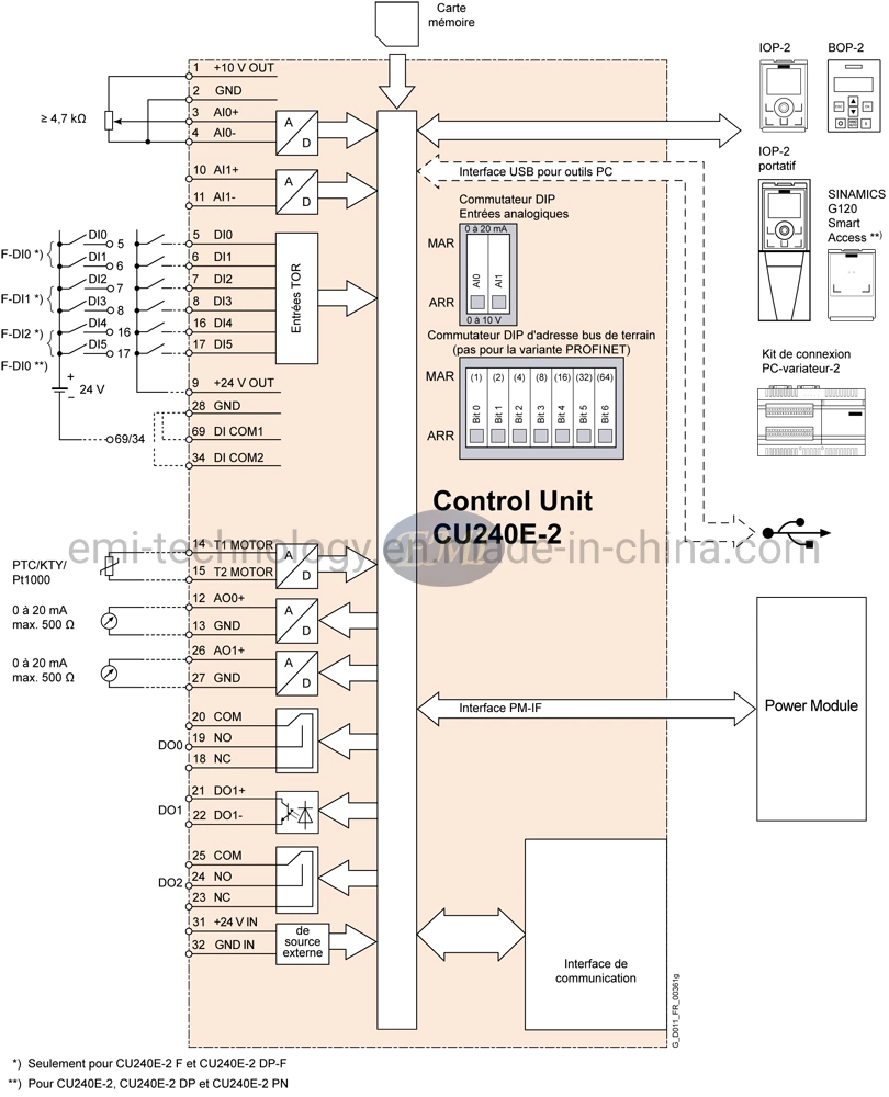
| Terminal No. | Signal | Features |
|---|---|---|
| Digital inputs (DI) - Standard | ||
| 5 ... 8, 16, 17 | DI0 … DI5 | Freely programmable (isolated) 5.5 mA/24 V |
| 69 | DI COM1 | Reference potential for digital inputs 0, 2, 4, 6 |
| 34 | DI COM2 | Reference potential for digital inputs 1, 3, 5, 7 |
| Digital inputs (DI) - Fail-safe (formed from two standard inputs using the appropriate parameter setting) | ||
| 16, 17 | F-DI0 | Fail-safe digital inputs, 2 channels (redundant), freely programmable (isolated) 5.5 mA/24 V |
| The following are only available for CU240E2 F, CU240E2 DPF and CU240E2 PNF | ||
| 5, 6 | F-DI0 | Fail-safe digital inputs, 2 channels (redundant), freely programmable (isolated) 5.5 mA/24 V |
| 7, 8 | F-DI1 | Fail-safe digital inputs, 2 channels (redundant), freely programmable (isolated) 5.5 mA/24 V |
| 16, 17 | F-DI2 | Fail-safe digital inputs, 2 channels (redundant), freely programmable (isolated) 5.5 mA/24 V |
| Digital outputs (DO) | ||
| 18 | DO0, NC | Relay output DO0 NC contact (0.5 A, 30 V DC) |
| 19 | DO0, NO | Relay output DO0 NO contact (0.5 A, 30 V DC) |
| 20 | DO0, COM | Relay output DO0 Common contact (0.5 A, 30 V DC) |
| 21 | DO1+ | Transistor output DO1 Positive (0.5 A, 30 V DC) |
| 22 | DO1- | Transistor output DO1 Negative (0.5 A, 30 V DC) |
| 23 | DO2, NC | Relay output DO2 NC contact (0.5 A, 30 V DC) |
| 24 | DO2, NO | Relay output DO2 NO contact (0.5 A, 30 V DC) |
| 25 | DO2, COM | Relay output DO2 Common contact (0.5 A, 30 V DC) |
| Analog inputs (AI) | ||
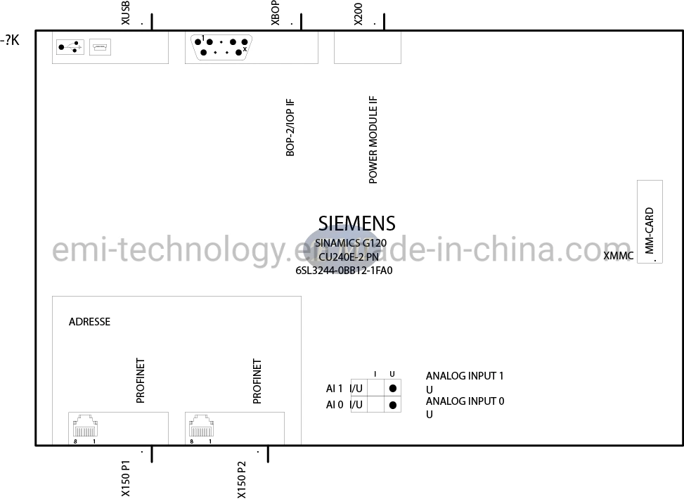
| 3 | AI0+ | Differential input, switchable between current, voltage Value range: 0 ... 10 V, -10 ... +10 V, 0/2 ... 10 V, 0/4 ... 20 mA |
| 4 | AI0- | |
| 10 | AI1+ | Differential input, switchable between current, voltage Value range: 0 ... 10 V, -10 ... +10 V, 0/2 ... 10 V, 0/4 ... 20 mA |
| 11 | AI1- | |
| Analog outputs (AO) | ||
| 12 | AO0+ | Non-isolated output Freely programmable Value range: 0 ... 10 V; 0/4 ... 20 mA |
| 13 | GND | Reference potential of the AO0/internal electronics ground |
| 26 | AO1+ | Non-isolated output Freely programmable Value range: 0 ... 10 V; 0/4 ... 20 mA |
| 27 | GND | Reference potential of the AO1/internal electronics ground |
| PTC/KTY interface | ||
| 14 | T1 MOTOR | Positive input for motor temperature sensor Type: PTC, Pt1000, KTY, bimetal |
| 15 | T2 MOTOR | Negative input for motor temperature sensor |
| Power supply | ||
| 9 | +24 V OUT | Power supply output 24 V DC, max. 100 mA |
| 28 | GND | Reference potential of the power supply/internal electronics ground |
| 1 | +10 V OUT | Power supply output 10 V DC ±0.5 V, max. 10 mA |
| 2 | GND | Reference potential of the power supply/internal electronics ground |
| 31 | +24 V IN | Power supply input 20.4 ... 28.8 V DC, max. 1500 mA |
| 32 | GND IN | Reference potential of the power supply input |