
 Complaint

Menu window No. | Function |
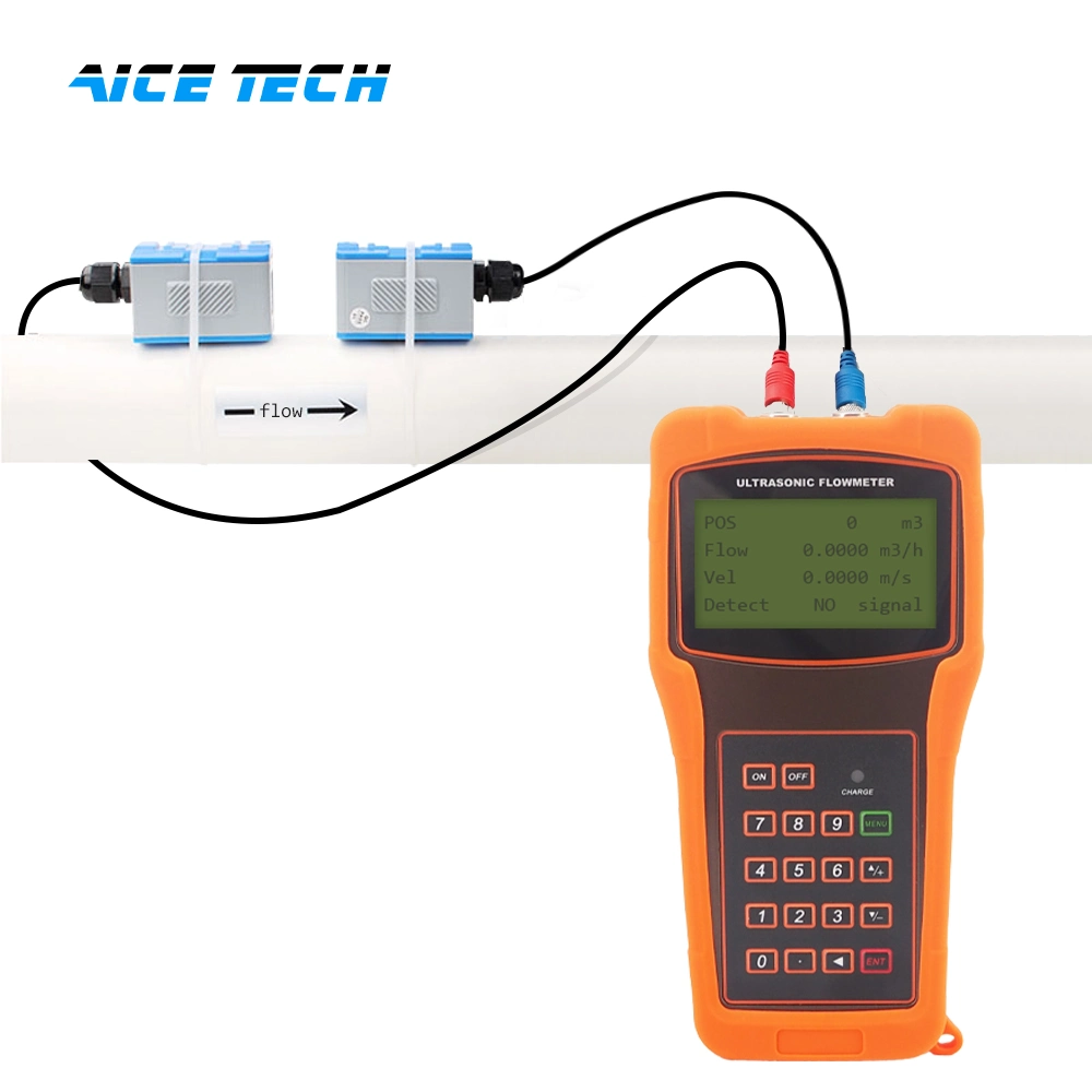
| M00 | Display three positive negative net totalizers, signal strength, signal quality and working status |
| M01 | Display POS totalizer, flow rate, velocity, signal strength, signal quality and working status |
| M02 | Display NEG totalizer, flow rate, velocity, signal strength, signal quality and working status |
| M03 | Display NET totalizer, flow rate, velocity, signal strength, signal quality and working status |
| M04 | Display date and time, flow rate, signal strength, signal quality and working status |
| M05 | Display date and time, velocity, signal strength, signal quality and working status |
| M06 | Display the wave shape of the receiving signal |
| M07 | Display the battery terminal voltage and its estimated lasting time |
| M08 | Display the all the detailed working status, signal strength, signal quality |
| M09 | Display today's total flow, velocity, signal strength, signal quality and working status |
| M10 | Window for entering the outer perimeter of the pipe |
| M11 | Window for entering the outer diameter of the pipe 0 to 6000mm is the allowed range of the value. |
| M12 | Window for entering pipe wall thickness |
| M13 | Window for entering the inner diameter of the pipe |
M14 | Window for selecting pipe material Standard pipe materials (that the user need not know the speed ) include: (0) carbon steel (1) stainless steel (2) cast iron (3) ductile iron (4) copper (5) PVc (6) aluminum (7) asbestos (8) fiberglass |
| M15 | Window for entering the pipe material speed only for non-standard pipe materials |
M16 | Window for selecting the liner material, select none for pipes without any liner Standard liner materials that the user need not know the speed include: (1) Tar Epoxy (2) Rubber (3) Mortar (4) Polypropylene (5) Polystryol (6)Polystyrene (7) Polyester (8) Polyethylene (9) Ebonite (10) TFN |
| M17 | Window for entering the liner material speed only for non-standard liner materials |
| M18 | Window for entering the liner thickness, if there is a liner |
| M19 | Window for entering the ABS thickness of the inside wall of the pipe |
M20 | Window for selecting fluid type For standard liquids that the user need not know the liquid speed include: (0) Water (1) Sea Water (2) Kerosene (3) Gasoline (4) Fuel oil (5) crude Oil (6) Propane at -45c (7) Butane at 0c (8)Other liquids (9) Diesel Oil (10)caster Oil (11)Peanut Oil (12) #90 Gasoline (13) #93 Gasoline (14) Alcohol (15) Hot water at 125c |
| M21 | Window for entering the fluid sonic velocity only for non-standard liquids |
| M22 | Window for entering the viscosity of the non-standard liquids |
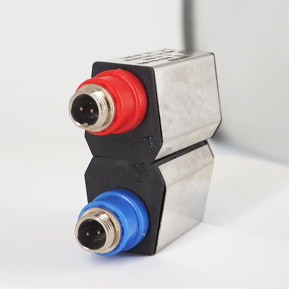
M23 | Window for selecting the proper transducers There are 14 different types of transducers for selection. If the user-type-transducers are used, 4 user type wedge parameters, which will be prompted by the software, should be entered following. If the π type transducers are used, 3 π type transducers and pipe parameters should be entered following. |
M24 | Window for selecting the transducer mounting methods Four methods can be selected: (0) V-method (1) Z-method (2) N-method (3) W-method |
| M25 | Display the transducer mounting spacing |
| M26 | Entry to store the parameter configuration into the internal NVRAM |
| M27 | Entry to load one set of saved parameters |
M28 | Select YES or NO for the instrument to determine whether or not to hold (or to keep) the last correct value when poor signal condition occurs. YES is the default setup |
| M29 | Enter a value ranging from 000 to 999. 0 is the default value |
| M30 | Window for selecting unit system. Default value is 'Metric'. The change from English to Metric or vice versa will not affect the unit for totalizers. |
M31 | Window for selecting flow rate that will be used by the instrument afterward. Flow rate can be in
|
| M32 | Window for selecting the totaliziers' working unit |
| M33 | Select totalizer multiplier The multiplier ranges from 0.001 to 10000 |
| M34 | Turn on or turn off the NET totalizer |
| M35 | Turn on or turn off the POS totalizer |
| M36 | Turn on or turn off the NEG totalizer |
| M37 |
|
| by pressing the dot key followed by the backspace key. Take care or make note on the parameters before doing the restoration | |
| M38 | Press-a-key-to-run or to stop totalizer for easier calibration |
| M39 | Operational interface language selection in chinese and English. This selection makes it possible that more than 2 billions of people on the world can read the menu. |
| M40 | Flow rate damper for a stable value. The input range is 0 to 999 seconds. 0 means there is no damping. Default value is 10 seconds |
| M41 | Lower flow rate cut-off to avoid invalid accumulation. |
| M42 | Zero point setup under the condition when there is no liquid running inside the pipe. |
| M43 | clear the zero point set by the user, and restore the zero point set by the manufacturer |
| M44 | Set up a manual flow bias. Generally this value should be 0. |
| M45 | Scale factor for the instrument. The default value is '1'. Keep this value as '1', when no user calibration has been made. |
M46 | Network environment Identification Number. Any integer can be entered except 13(0DH, carriage return), 10 (0AH, line feeding), 42 (2AH), 38, 65535. Every set of the instrument ina network environment should havea unique IDN. Please refer to the chapter for communication. |
| M47 | System locker to avoid modification of the parameters |
| M48 | Not used |
| M49 | communication tester |
| M50 | "Option" selection for the built-in logger. It also functions as the switch of logger |
| M51 | Time setup for the data logger |
M52 |
|
M53 | Logger buffer viewer. It functions as a file editor. Use Dot, backspace UP and DN keys to browse the buffer. If the logger is ON, the viewer will automatically refresh once new data are stored |
| M54 | Not used |
| M55 | Nod used |
| M56 | Not used |
| M57 | Not used |
| M58 | Not used |
| M59 | Not used |
M60 | 99-year calendar. Press ENT for modification. Use the dot key to skip the digits that need no adjusting. |
M61 | Display Version information and Electronic Serial Number (ESN) that are unique for each TDS-100 series flow meter. The users can employ the ESN for instrumentation management |
| M62 | RS-232 setup. Baud rate can be 75 to 115200 bps |
| M63 | Not used |
| M64 | Not used |
| M65 | Not used |
| M66 | Not used |
| M67 | Input the frequency range for the frequency output. The biggest range is 0Hz-9999Hz. Default value is 1-1001 Hz |
| M68 | Enter a flow rate value that corresponds to lower frequency |
| M69 | Enter a flow Rate value that corresponds to higher frequency |
| M70 | LcD display backlight control. The entered value indicates how many seconds the backlight will be on with every key pressing. |
| M71 | LcD contrast control. The LcD will become darker when a small value is entered. |
| M72 | Working timer. It can be cleared by pressing ENT key, and then select YES. |
M73 | Enter Lower Flow Rate value that will trigger the #1 Alarm. There are two virtual alarms in the system. By "virtual" we mean that the user must redirect the output of the alarms by setuping the output hardware in M78 and M77 |
| M74 | Enter the higher flow rate value that will trigger the #1 Alarm. |
| M75 | Enter the lower flow rate value that will trigger the #2 Alarm. |
| M76 | Enter the higher flow rate value that will trigger the #2 Alarm. |
M77 | Buzzer setup. If a proper input source is selected, the buzzer will beep when the trigger event occurs |
| M78 | OcT (Open collect Transistor Output) setup By selecting a proper input source, the OcT hardware will close when the trigger event occurs |
| M79 | Not used |
| M80 | Work as a keypad and display for another handhold set by RS-232 connected with the handset |
| M81 | Not used |
| M82 | Date totalizer |
| M83 | Not used |
| M84 | Not used |
| M85 | Not used |
| M86 | Not used |
| M87 | Not used |
| M88 | Not used |
| M89 | Not used |
| M90 | Display signal strength, signal quality, time ratio on the upper right corner. |
M91 | Displays the Time Ratio between the Measured Total Transit Time and the calculated time. If the pipe parameters are entered correctly and the transducers are properly installed, the ratio value should be in the range of 100 ±3%. Otherwise the entered parameters and the transducer installation should be checked. |
M92 | Displays the estimated fluid sound velocity. If this value has an obvious difference with the actual fluid sound speed, pipe parameters entered and the transducer installation should be checked again. |
| M93 | Displays total transit time and delta time(transit time difference) |
| M94 | Displays the Reynolds number and the pipe factor used by the flow rate program. |
| M95 | Not used |
| M96 | Not used |
| M97 | command to record the pipe parameters entered by the user either to the built-in data logger or to RS-232c serial interface |
| M98 | command to record the diagnostic information either to the built-in data logger or to RS-232c serial interface |
| M99 | command to copy the current display either to the built-in data logger or to RS-232c serial interface |
| M+0 | Browse the 64 recorded instrument power-on and power-off date and time with the flow rate at the time of power on and off |
| M+1 | Displays the total working time of the instrument |
| M+2 | Displays the last power-off date and time |
| M+3 | Displays the last power-off flow rate |
| M+4 | Displays the times of instrument powered on(the instrument has been powered on) |
M+5 | A scientific calculator for the convenience of field working. All the values are in single accuracy. The drawback is that the user can't operate it by direct key-pressing |
| M+6 | Not used |
| M+7 | Not used |
| M+8 | Not used |
| M+9 | Not used |
| M-0 | Entry to hardware adjusting windows only for the manufacturer |