Description
G1 series diaphragm compressor feature:Small diaphragm compressors:
Structure: Z,L, P.D type
Lubrication: Splash
Oil type: complusory oil supplement
cooling way: water cooled or air cooled
maintenance maximum weight per piece: 80kg
maintenance maximum space: the circle shall be not less than 1 m
| | | Flow rate | Inlet pressure | Outlet pressure | Water waste | speed of crankshaft | Motor Power | Size | Machine weight |
| No: | | Nm3/h | Mpa(G) | Mpa(G) | L/h | r/min | KW | LxWxH mm | kg |
| 1 | GD0-3/200 | 3 | normal pressure | 20 | none | 750 | 2.2 | 600x500x400 | 200 |
| 2 | GL1-5/200 | 5 | normal pressure | 20 | 300 | 600 | 3 | 1350x600x950 | 550 |
| 3 | GL1-10/13 | 10 | normal pressure | 1.3 | 300 | 600 | 3 | 1350x600x950 | 550 |
| 4 | GL1-10/13-200 | 10 | 1.3 | 20 | 300 | 600 | 3 | 1350x600x950 | 550 |
| 5 | GL1-5/1-160 | 5 | 0.1 | 16 | 300 | 450 | 3 | 1350x600x950 | 550 |
| 6 | GL1-10/4-160 | 10 | 0.4 | 16 | 400 | 600 | 4 | 1350x600x950 | 520 |
| 7 | GL1-8/2.5-160 | 8 | 0.25 | 16 | 400 | 400 | 3 | 1350x600x950 | 520 |
| 8 | GL1-10/6-160 | 10 | 0.7 | 15 | 400 | 400 | 4 | 1350x600x950 | 520 |
| 9 | GL1-5/6-200 | 5 | 0.6 | 20 | 300 | 400 | 3 | 1350x600x950 | 520 |
| 10 | GL1-10/6-160 | 10 | 0.6 | 16 | 400 | 400 | 4 | 1350x600x950 | 520 |
| 11 | GL1-5/13-400 | 5 | 1.3 | 40 | 300 | 400 | 3 | 1350x600x950 | 500 |
| 12 | GL1-15/10-150 | 15 | 1 | 15 | 400 | 450 | 4 | 1350x600x950 | 520 |
| 13 | GL1-10/7-320 | 10 | 0.7 | 32 | 400 | 450 | 4 | 1350x600x950 | 520 |
| 14 | GL1-5/4-350 | 5 | 0.4 | 35 | 300 | 400 | 3 | 1350x600x950 | 520 |
| 15 | GZ1-5/13 | 5 | normal pressure | 1.3 | 200 | 450 | 1.5 | 1100x600x950 | 450 |
| 16 | GZ1-5/13-200 | 5 | 1.3 | 20 | 200 | 450 | 1.5 | 1100x600x950 | 420 |
| 17 | GZ1-5/30-400 | 5 | 3 | 40 | 300 | 400 | 3 | 1100x600x950 | 400 |
| 18 | GZ1-70/30-35 | 70 | 3 | 3.5 | 200 | 400 | 4 | 1100x600x950 | 420 |
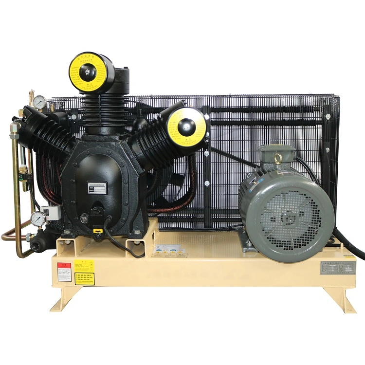
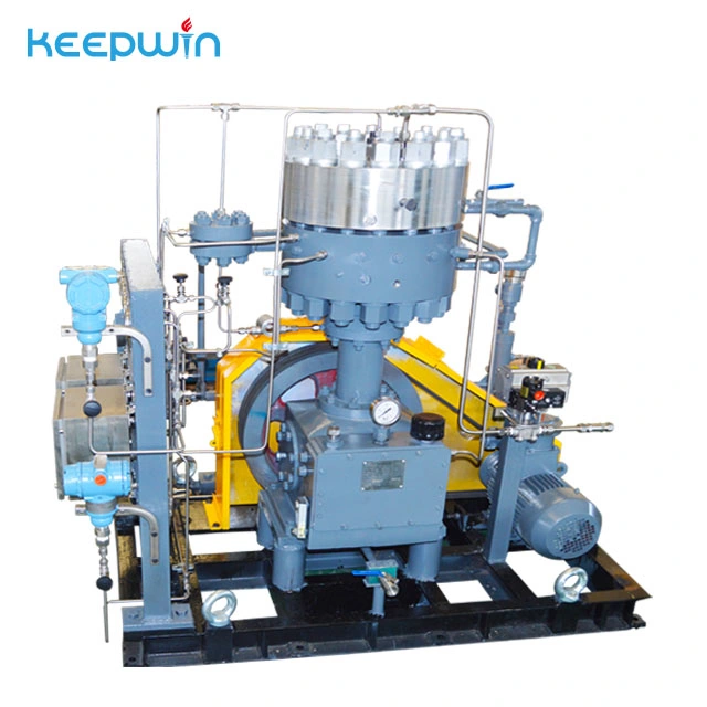
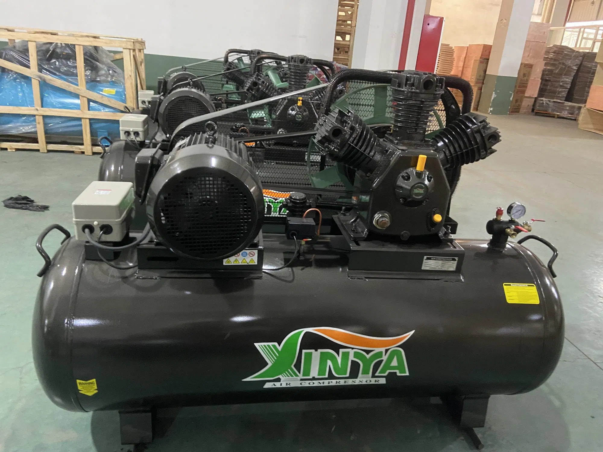
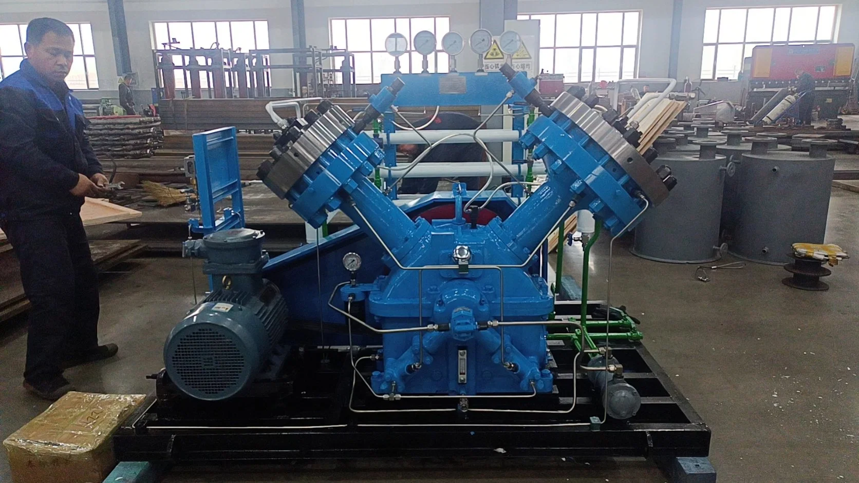
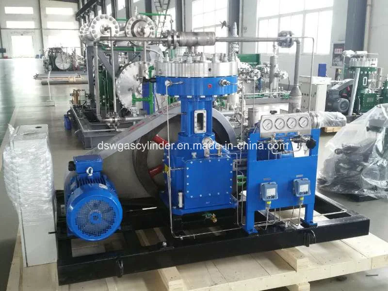
General information of structure Diaphragm compressor mainly consists of crankcase, connecting rod, cross-head, piston, cylinder body, cooler and its pipeline, base plate, instrumentation, electric motor etc. The compressor structure is divided into 4 types---L, Z, V and D, according to cylinder body arrangement.
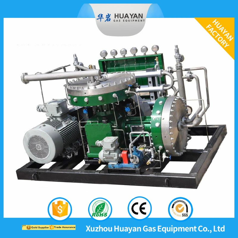
L type diaphragm compressor's vertical and horizontal cylinders form L. (Please refer to the picture)
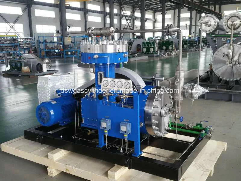
Z type diaphragm compressor only consists of vertical cylinders, and this structure looks like the letter "Z". (Please refer to the picture)
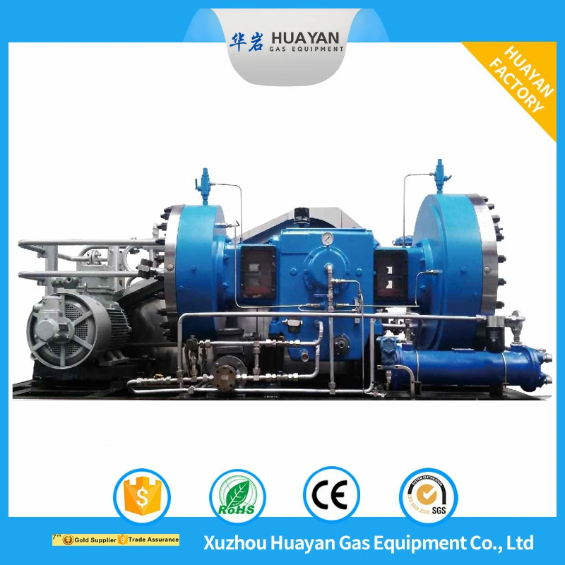
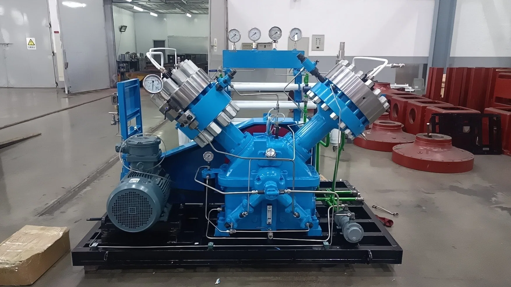
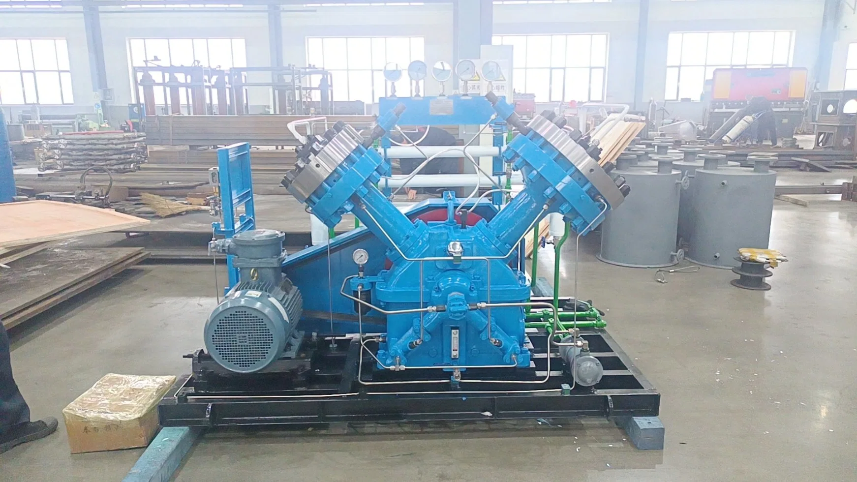
V type diaphragm compressor's left and right cylinders form V. (Please refer to the picture)
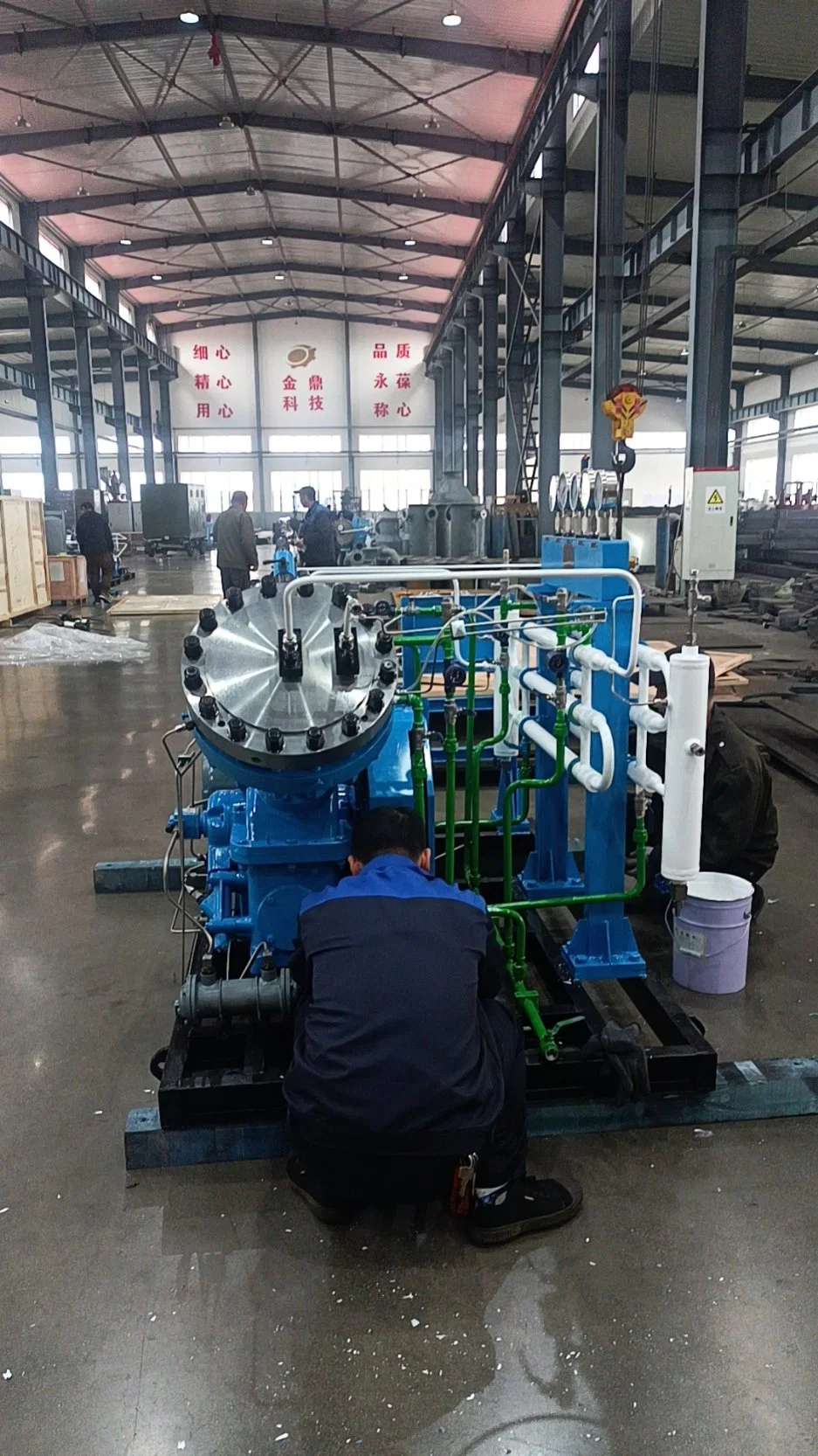
D type diaphragm compressor is the balanced opposed frame, the cylinder body number can be 2, 3 or 4. (Please refer to the picture. This is the 4 cylinders type)
Main technical dataCylinder All the cylinders comprise upper plate, diaphragms, and cylinder body etc. The diaphragms are clamped between the cylinder cover and cylinder body. The cylinder cover and cylinder body each has a concave recess hollowed out in their contacting faces. The gas cylinder is formed between cylinder cover concave recess and diaphragms. Both suction valve and discharge valve are fitted on the upper plate. Among of them, the discharge valve is located on the center of the upper plate. The evenly located small oil holes are on the cylinder body to deliver the oil pressure inside the oil cylinder to the diaphragms.
Pressure Regulating Valve The oil pressure of oil cylinder is regulated by the tension of the valve spring.In case the oil pressure is higher than the regulated value, turn the regulating bolt counter-clockwise to loosen the spring tension, but turn the regulating bolt clockwise to tighten the spring, when the oil pressure is lower than the regulated value. When the oil pressure meets the required value, the regulating bolt must be locked with a lock-nut. The oil pressure of the oil cylinder shall always be higher than the discharge pressure by 15~20%. But the oil and gas differential pressure shall not be lower than 0.3MPa or higher than 1.5MPa.
CoolerThe cooler structure is the double-wall pipe type. The circular space between the outer and inner pipe is the cooling water passage and the inner pipe is the gas passage. Normally the water inlet port is at the lower side and the water outlet port is at the upper side. The flow direction of cooling water and gas is on the contrary.
Oil Pressure Measuring Device The measuring device of oil cylinder discharge pressure consists of shock-proof pressure gauge, check valve and unloading valve. The case of the pressure gauge is totally airproof and filled with damping liquid. The inner devices of gauge is immersed in the liquid, which makes the pressure gauge hands stable through the function of the viscosity of damping liquid. The unloading valve is fitted under the gauge to discharge the remained air in the oil pipeline and to unload the oil pressure gauge. Also the check valve connecting with oil cylinder through pipeline is fitted under the unloading valve.
Oil pipes Oil pipes consist of lube oil pipe and oil pressure secure system.
The lubrication for the driving device adopts gear oil pump circulation pressure lubricating. The lube oil stored in the frame oil tank enters into the gear oil pump after being filtered and is pressed into the oil holes in the crankshaft through the gear oil pump to lubricate the crankshaft friction surface. At the same time, part of the lube oil reaches the crosshead pin and crosshead along the oil holes in the connecting rod to lubricate the friction surface. The oil pressure of gear oil pump shall be kept between 0.3~0.5Mpa, and the bearings at the two ends of crankshaft is splash lubricated.
Oil pressure secure system consists of oil compensating pipe, pressure-measuring pipe and oil return pipe. The oil output from the oil compensating pump will supplement oil for compressor cylinders through the oil compensating pipe and the excess oil returns to the crankcase through the pressure-regulating valve.
Gas pipesThe gas enters into compressor through inlet port to be compressed and enters into the clients' system after cooling by the cooler.

 Complaint