 Complaint

| Wavelength: | 1310nm | Data Rate: | 40G |
|---|---|---|---|
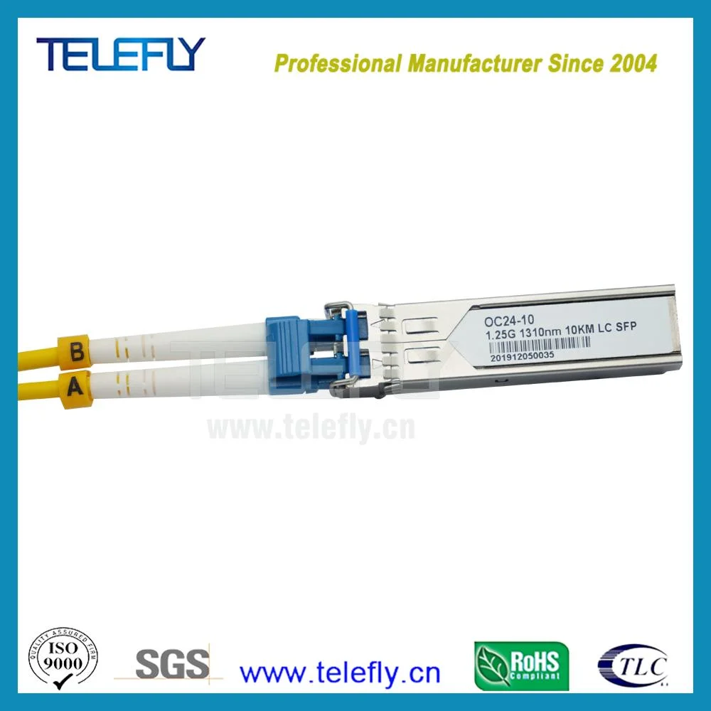
| Transmission Distance: | 10KM | Interface: | Duplex LC |
| Certification: | CE RoHS FCC | Brand: | Can Be Customized |
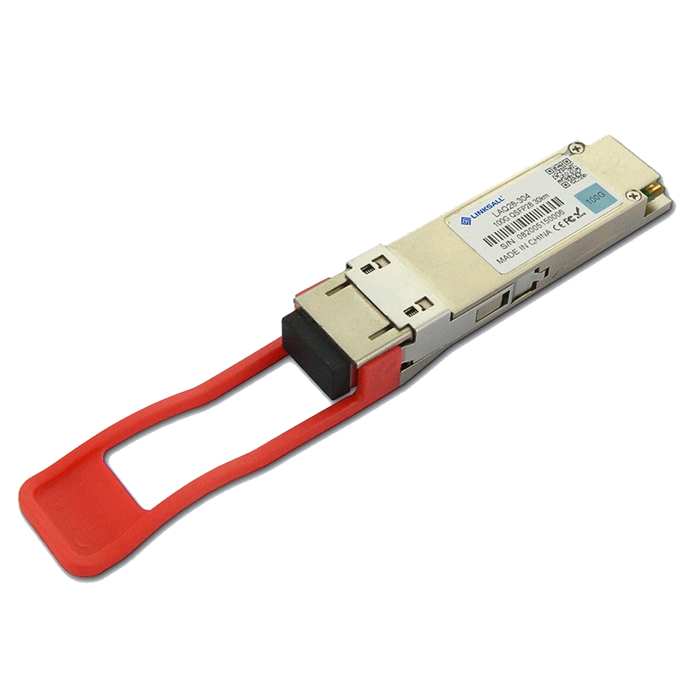
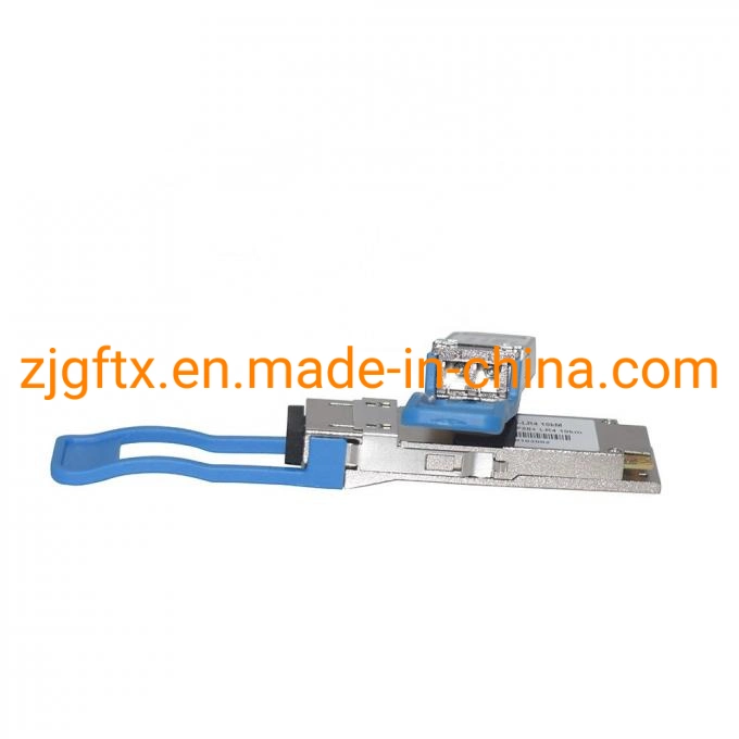
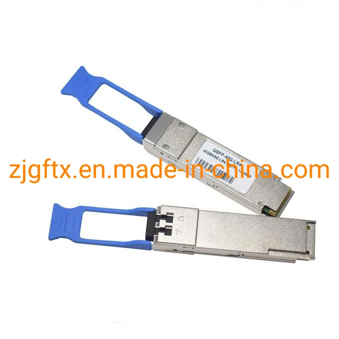
| Form Factor: | QSFP+ | DDM/DOM: | Supported |
| Transimitter Type: | DFB CWDM | Power Consumption: | 3.5W |
| High Light: | QSFP+ Fiber Ethernet Transceiver,1310nm Cisco Fiber Transceiver | ||
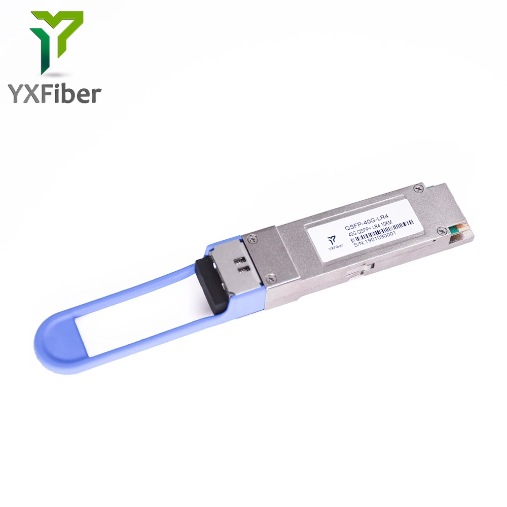
Cisco compatiable 40GBASE LR4 QSFP+ 1310nm 10KM LC DOM single mode fiber transceiver
40GBASE LR4 QSFP+ is designed to operate over single-mode fiber system using 4X10 CWDM channel in 1310 band and links up to 10km. The module converts 4 inputs channel of 10Gb/s electrical data to 4 CWDM optical signals, and multiplexes them into a single channel for 40Gb/s optical transmission. Reversely, on the receiver side, the module optically de-multiplexes a 40Gb/s input into 4 CWDM channels signals, and converts them to 4 channel output electrical data.
The central wavelengths of the 4 CWDM channels are 1271, 1291, 1311 and 1331 nm. It contains a duplex LC connector for the optical interface and a 38-pin connector for the electrical interface. Single-mode fiber (SMF) is applied in this module. This product converts the 4-channel 10Gb/s electrical input data into CWDM optical signals (light), by a 4-wavelength Distributed Feedback Laser (DFB) array. The 4 wavelengths are multiplexed into a single 40Gb/s data, propagating out of the transmitter module via the SMF. The receiver module accepts the 40Gb/s optical signals input, and de-multiplexes it into 4 CWDM 10Gb/s channels. Each wavelength light is collected by a discrete photo diode, and then outputted as electric data after amplified by a TIA.
Features
4 CWDM lanes Mux/Demux design
Up to 11.1Gbps Data rate per wavelength
Up to 10km transmission on SMF
Electrically hot-pluggable
Digital Diagnostics Monitoring Interface
Compliant with QSFP+ MSA with LC connector
Case operating temperature range:0°C to 70°C RoHS Compliant.
Power dissipation < 3.5 W
Applications
40G Ethernet
Data Center and LAN
| Product Description |
| 4 CWDM, 40Gbps, 10km, 0?C ~ +70?C, Ethernet Version, DDM |
| 4 CWDM, 40Gbps, 20km, 0?C ~ +70?C, Ethernet Version, DDM |
| 4 CWDM, 40Gbps, 30km, 0?C ~ +70?C, Ethernet Version, DDM |
| Parameter | Symbol | Min. | Typ. | Max. | Note |
| Storage Temperature(ºC) | Ts | -40 | - | 85 | |
| Storage Ambient Humidity(%) | HA | 5 | - | 95 | |
| Operating Relative Humidity(%) | RH | - | - | 85 | |
| Operating Relative Humidity(V) | VCC | -0.3 | - | 4 | |
| Signal Input Voltage(V) | Vcc-0.3 | - | Vcc+0.3 |
| Parameter | Symbol | Min. | Typ. | Max. | Note |
| Case Operating Temperature(ºC) | Tcase | 0 | - | 70 | Without air flow |
| Power Supply Voltage(V) | VCC | 3.14 | 3.3 | 3.47 | |
| Power Supply Current(mA) | ICC | - | 800 | ||
| Data Rate(Gbps) | BR | 10.3125 | Each channel | ||
| Transmission Distance(km) | TD | - | 10 | ||
| Coupled fiber | Single mode fiber | 9/125um SMF | |||
| Parameter | Symbol | Min. | Typ. | Max. | Note. |
| Transmitter | |||||
| Wavelength Assignment(nm) | λ0 | 1264.5 | 1271 | 1277.5 | |
| λ1 | 1284.5 | 1291 | 1297.5 | ||
| λ2 | 1304.5 | 1311 | 1317.5 | ||
| λ3 | 1324.5 | 1331 | 1337.5 | ||
| Total Output. Power(dBm) | POUT | 8.3 | |||
| Average Launch Power Per lane(dBm) | -7 | 2.3 | |||
| Spectral Width (-20dB)(nm) | σ | 1 | |||
| SMSR(dB) | 30 | ||||
| Optical Extinction Ratio(dB) | ER | 3.5 | |||
| Average launch Power off per lane(dBm) | Poff | -30 | |||
| Transmitter and Dispersion Peanlty(dB) | TDP | 2.3 | |||
| RIN(dB/Hz) | RIN | -128 | |||
| Output Eye Mask | RIN | ||||
| Receiver | |||||
| Rx Sensitivity per lane(OMA)(dBm) | RSENS | -11.5 | 1 | ||
| Input Saturation Power (Overload)(dBm) | Psat | 3.3 | |||
| Receiver Reflectance (dB) | Rr | -2.6 | |||
Notes:
1.Measured with a PRBS 231-1 test pattern, @10.325Gb/s, BER<10-12 .
| Parameter | Symbol | Min. | Typ. | Max. | Note. |
| Supply Voltage(V) | Vcc | 3.14 | 3.3 | 3.46 | |
| Supply Current(mA) | Icc | 760 | |||
| Transmitter | |||||
| Input differential impedance(Ω) | Rin | 100 | 1 | ||
| Differential data input swing(mV) | Vin,pp | 180 | 1000 | ||
| Transmit Disable Voltage(V) | VD | Vcc-1.3 | Vcc | ||
| Transmit Enable Voltage(V) | VEN | Vee | Vee+ 0.8 | 2 | |
| Transmit Disable Assert Time(us) | 10 | 2 |
Notes:
1.Connected directly to TX data input pins. AC coupled thereafter.
2.Or open circuit.
3.Into 100 ohms differential termination.
4.20 - 80 %.
5.Loss Of Signal is LVTTL. Logic 0 indicates normal operation; logic 1 indicates no signal detected.
6.Receiver sensitivity is compliant with power supply sinusoidal modulation of 20 Hz to 1.5 MHz up to specified value applied through the recommended power supply filtering network.