 Complaint

| Description | |
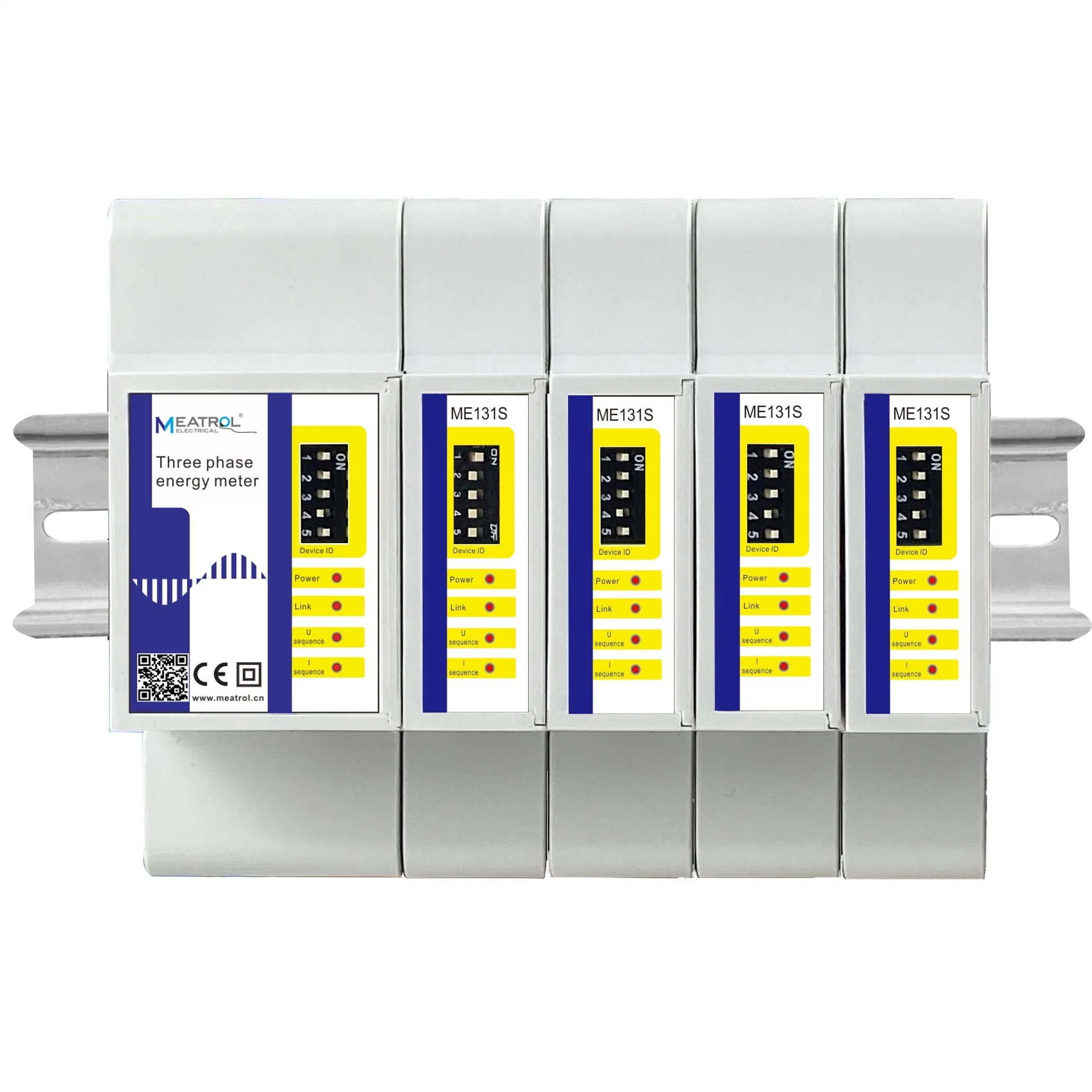
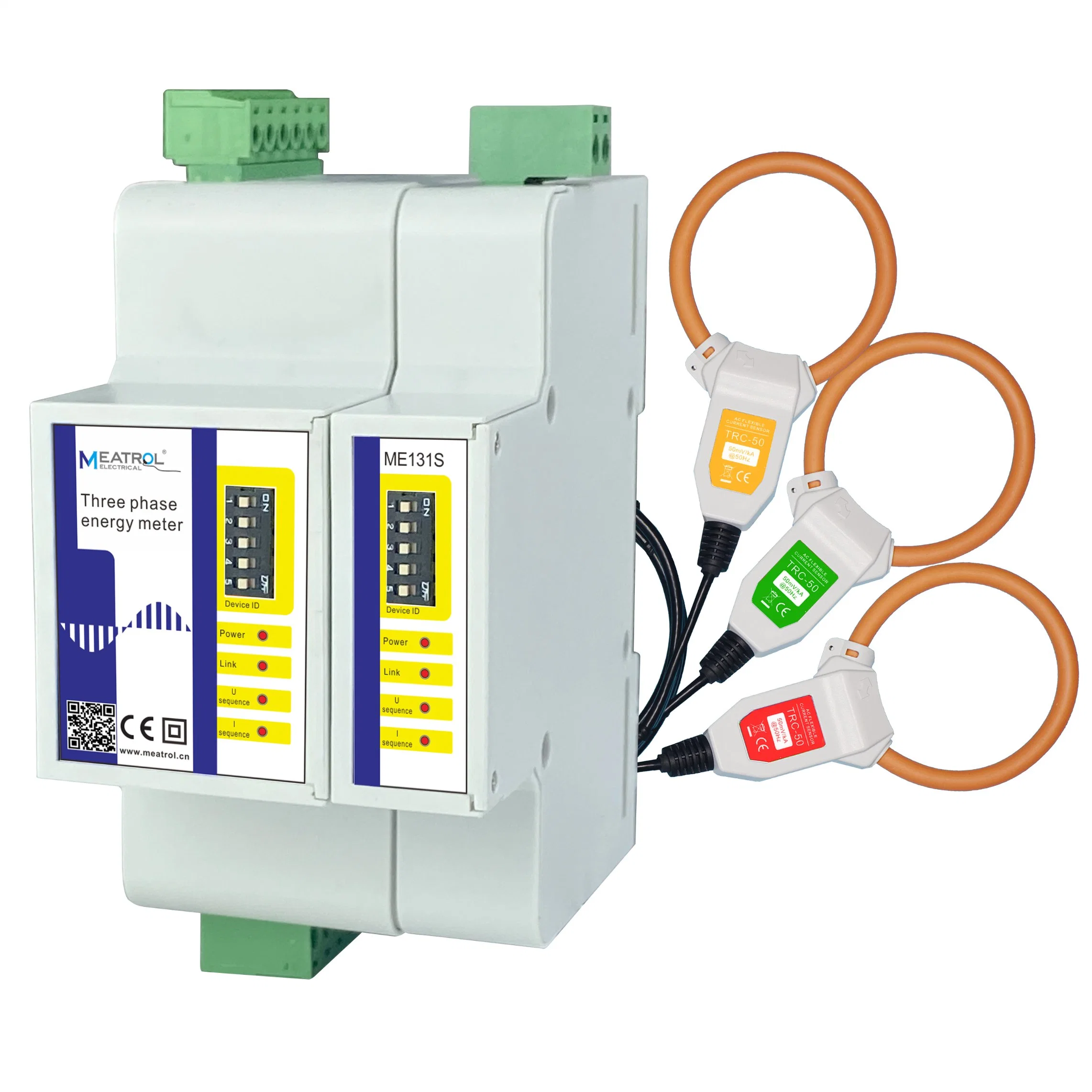
| Mounting type | Din Rail |
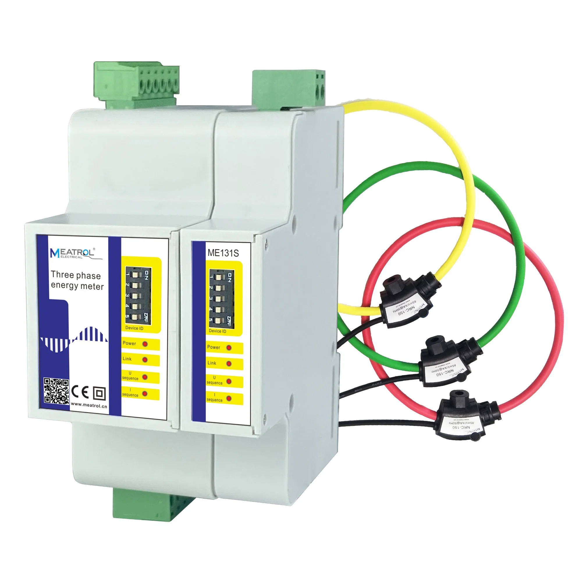
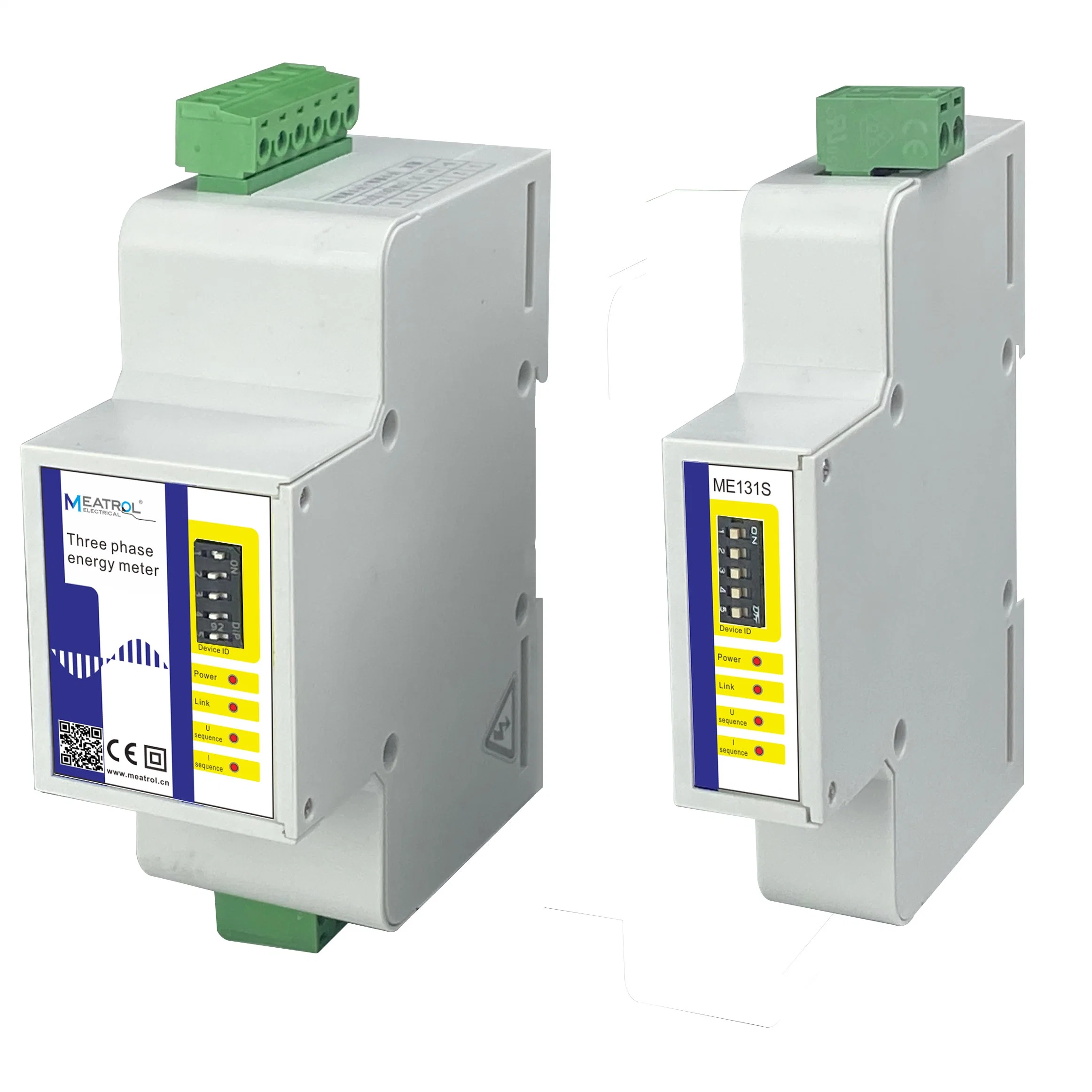
| Model No. | Master meter: ME131M, Submeter: ME131S |
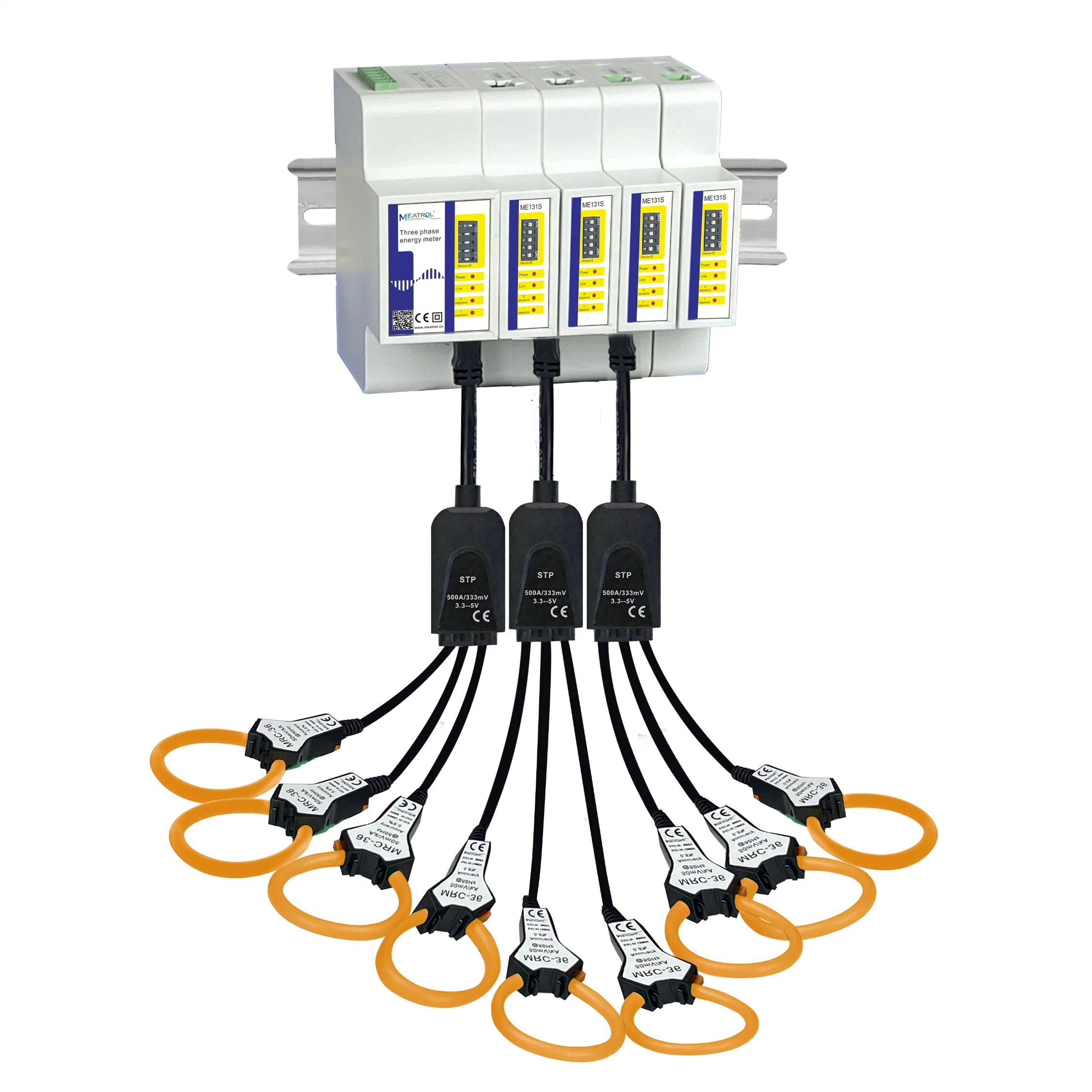
| Type of current sensor | Rogowski coil Voltage-output current transformer |
| Feature | Directly connect to Rogowski coil |
| Advantage | Wide current range, measurement without dismantling |
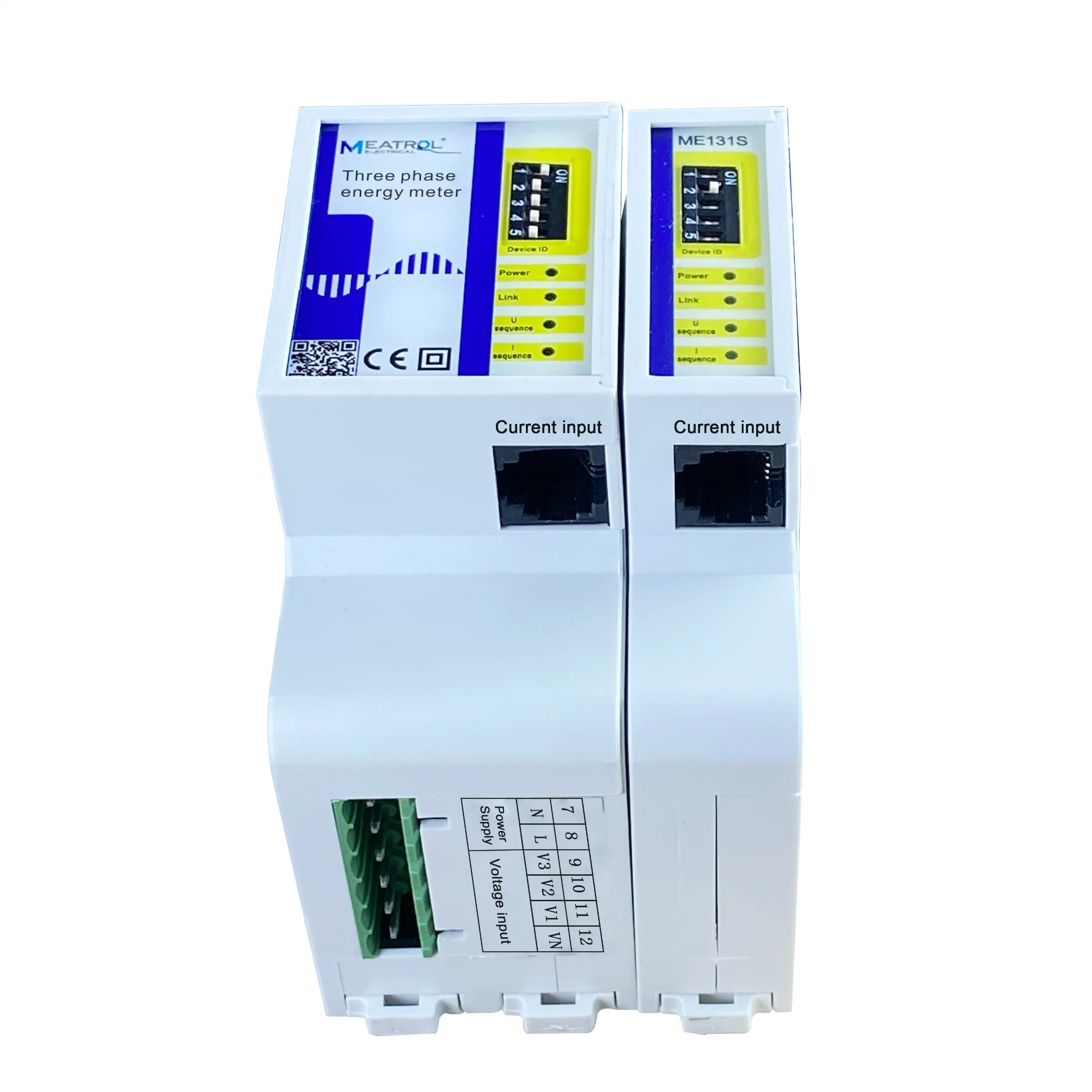
| Wiring system | 3P4W_3CT, 3P3W_3CT, 3P3W_2CT, 1P3W, 1P2W |
| Application field | Power analysis and energy consumption monitoring |
| Display screen | None |
| Weight | ME131M: 122g; ME131S: 59g |
| Dimension | ME131M: L*W*D 9.3*8.0*3.6CM; ME131S: L*W*D 9.3*8.0*1.81CM |
| Color | White |
| Current measurement | |
| Channel input voltage range | 0-900mVAC peak, 636 mV RMS |
| Measurement range | Different current sensors have different measuring ranges |
| Rogowski coil | 50mV/kA@50Hz(0-12000A), @60Hz(0-10000A) 85mV/kA@50Hz(0-7000A), @60Hz(0-6000A) 100mV/kA@50Hz(0-6000A), @60Hz(0-5000A) ... |
| Voltage-output CT | 0~99999A |
| Voltage measurement | |
| Measurement range | 0~600VAC |
| Maximum measured value | 720VAC |
| Digital signal | |
| Switching output | 1-circuit electromagnetic relay output, contact capacity: 3A 30V DC,3A 250V AC |
| Switching value input | Optocoupler isolation(5kVrms) |
| Communication | |
| RS485 Communication | One RS485 communication interface Interface type: two-wire half-duplex Communication baud rate: 2400bps~38400bps Protocol: Modbus-RTU |
| Power supply | |
| Power supply | 85~265VAC/110~370VDC, 45~60Hz (24V DC power supply version could be customized) |
| Maximum power consumption | ≤3.5VA |
| Instantaneous value | |
| Phase Voltage | U1, U2, U3, AVG, U0 (Zero sequence voltage) |
| Line Voltage | U12, U23, U31, AVG |
| Current | I1, I2, I3, AVG, In |
| Grid frequency | F1, F2, F3, ∑ |
| Power factor PF | PF1, PF2, PF3, ∑ |
| Fundamental power factor DPF | DPF1, DPF2, DPF3, ∑ |
| Active power | P1, P2, P3, ∑ |
| Reactive power | Q1, Q2, Q3, ∑ |
| Apparent power | S1, S2, S3, ∑ |
| Energy | |
| Active energy Pos. | EP1, EP2, EP3, ∑ |
| Active Energy Neg. | EP1, EP2, EP3, ∑ |
| Reactive Energy Pos. | EQ1, EQ2, EQ3, ∑ |
| Reactive energy Neg. | EQ1, EQ2, EQ3, ∑ |
| Apparent Energy | ES1, ES2, ES3, ∑ |
| Tariff Energy | ET1, ET2, ET3, ET4, ET5, ET6 |
| Harmonics | |
| Voltage Harmonic Distortion | Total harmonic(U1, U2, U3) Odd total harmonic(U1, U2, U3) Even total harmonic(U1, U2, U3) Sub-harmonic 1-50th(U1, U2, U3) |
| Current Harmonic Distortion | Total harmonic(I1, I2, I3) Odd total harmonic(I1, I2, I3) Even total harmonic(I1, I2, I3) K-factor(I1, I2, I3) Sub-harmonic 1-50th(I1, I2, I3) |
| Voltage Harmonic Value | Total harmonic(U1, U2, U3) Sub-harmonic 1-50th(U1, U2, U3) |
| Current Harmonic Value | Total harmonic(I1, I2, I3) Sub-harmonic 1-50th(I1, I2, I3) |
| Phase | |
| Phase sequence | Voltage, Current |
| Voltage angle | U1, U2, U3 |
| Current angle | I1, I2, I3 |
| Voltage-current angle | UI1, UI2, UI3 |
| Demand | |
| Demand | Total active power, total reactive power, total apparent power |
| Maximum demand of total active power | Maximum demand and time |
| Maximum demand of total reactive power | Maximum demand and time |
| Maximum demand of total apparent power | Maximum demand and time |
| Unbalance | |
| Voltage unbalance | Negative Sequence, zero Sequence |
| Current unbalance | Negative Sequence, zero Sequence |
| Max. & Min. | |
| Phase Voltage | Each phase and average |
| Line Voltage | Each phase and average |
| Current | Each phase and average |
| Active power | Each phase and total |
| Reactive power | Each phase and total |
| Apparent power | Each phase and total |
| Measurement Accuracy | ||
| Current measurement accuracy | 0.1%+ Current sensor accuracy | |
| Voltage measurement accuracy | ±0.2%(60V~600V AC) | |
| Grid frequency | ±0.01%(45~65Hz) | |
| Power factor | ±0.005 | |