Testing step: 1. Check the breakdown status of the cable with a multimeter, a rocking watch or other pressure resistant equipment,
and record the value of each core's insulation resistance against the ground or residual voltage breakdown.
2. Record the length,
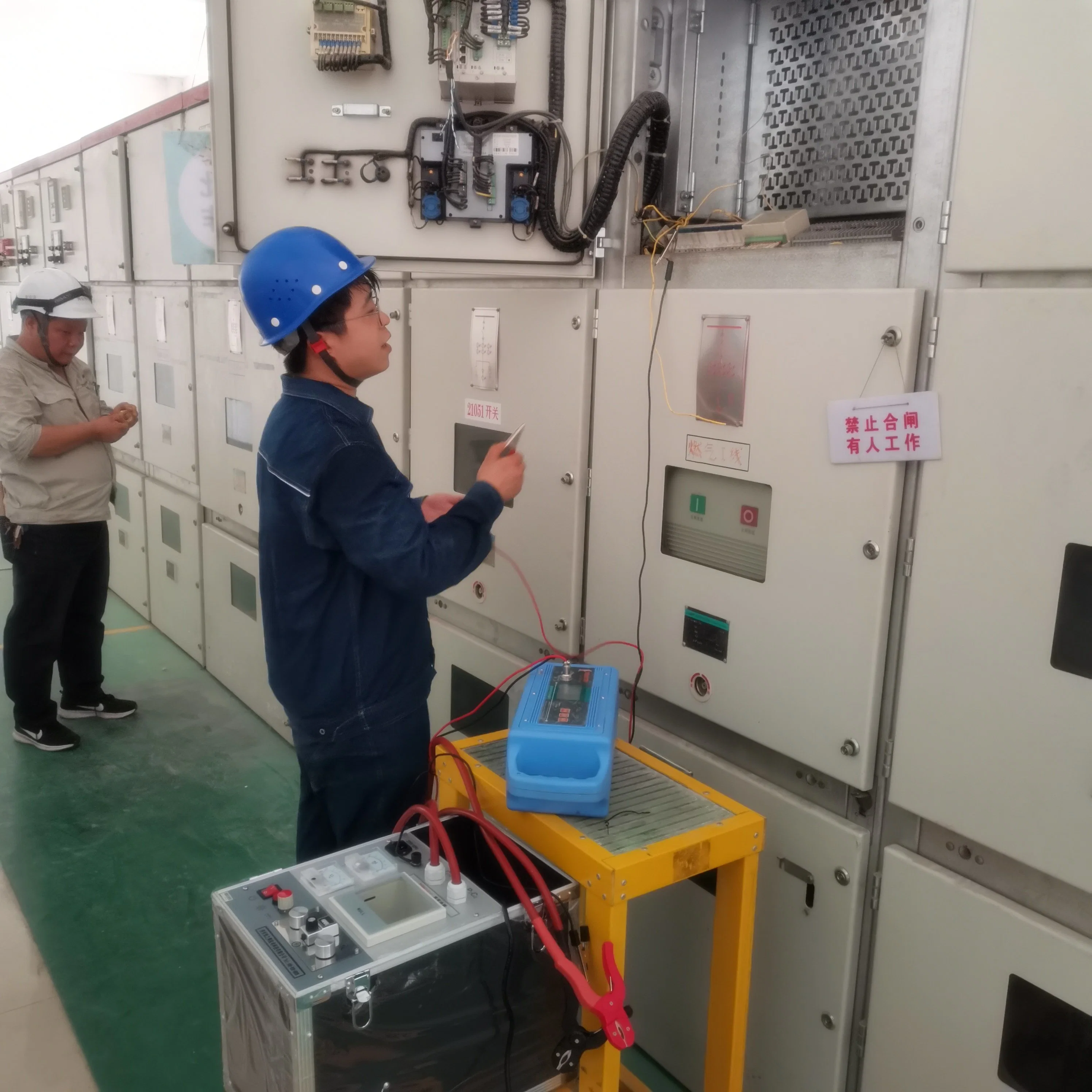
model, cross section and other parameters of the cable to be tested, and inspect the route along the cable laying path. In the
remote short-circuit fault cable and the auxiliary cable outlet terminal, leave one person at the remote monitoring to avoid
high-pressure injury.
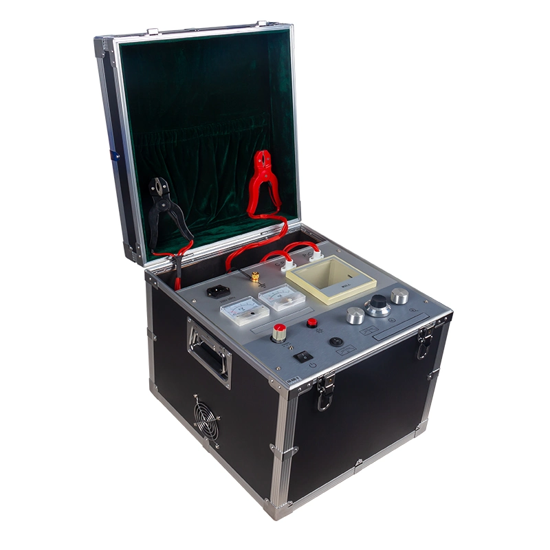
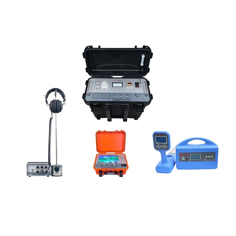
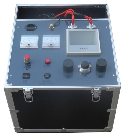
3. wiring. The ground of the instrument is reliably connected to the grounding body of the positioning site.
Ground rods are connected to the instrument ground. The measuring head (black clip) is connected to the faulty cable core and the
measuring end (red clip) is connected to the auxiliary cable core.
4. bridge zero (high voltage knob is not zero). Turn on the
power and rotate the zero button to zero the galvanometer.
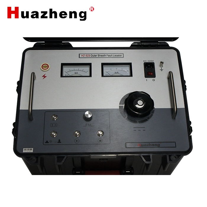
5. power supply connected to AC220V.
6. Boost pressure. Turn on the
power switch and the power indicator lights up. When the high pressure knob is turned counterclockwise, the zero position is
activated.
7. Turn the high pressure knob clockwise and watch the voltmeter and ammeter until the ammeter exceeds 5mA. If the
current is not stable, the voltage may continue to rise for a period of time to form a stable arc or conductive area, stabilizing
the current during the test.
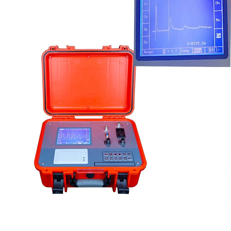
8, balance adjustment. Rotate the zoom knob clockwise to increase the sensitivity step by step until
the galvanometer deflects significantly but does not overshoot. Rotate the dial to make the galvanometer zero. (If the pointer is
to the left, rotate clockwise, the pointer is to the right, and counterclockwise). Take note of the reading P1 of the cymbal dial
at this time.
9, drop voltage, discharge. The clamp exchange position will be measured and steps (4) to (10) will be repeated to
obtain another reading P2, which should have P1+P2=1000
10. Calculation. Location of fault point X=2×L ×P1‰ Pay more attention to
the "2" in the formula. The auxiliary cable will double the number of cables involved in the calculation. 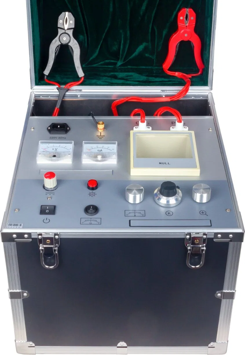

 Complaint