Description
Product Description
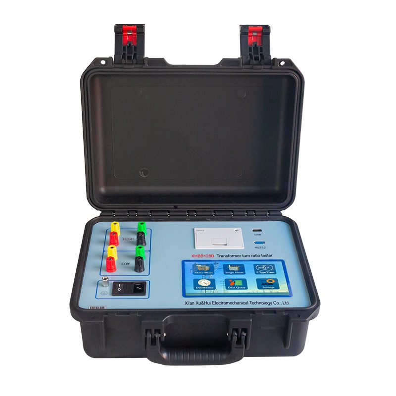
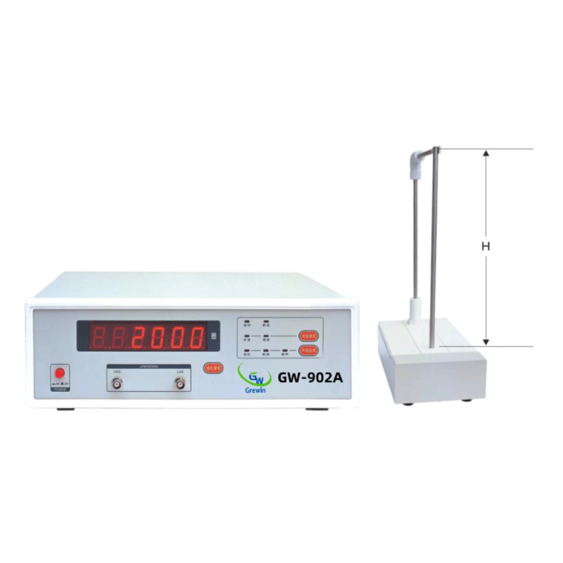
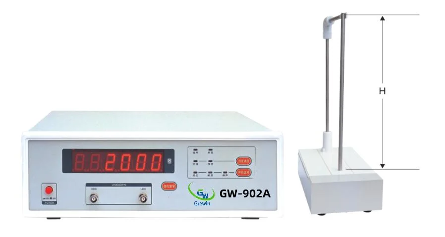
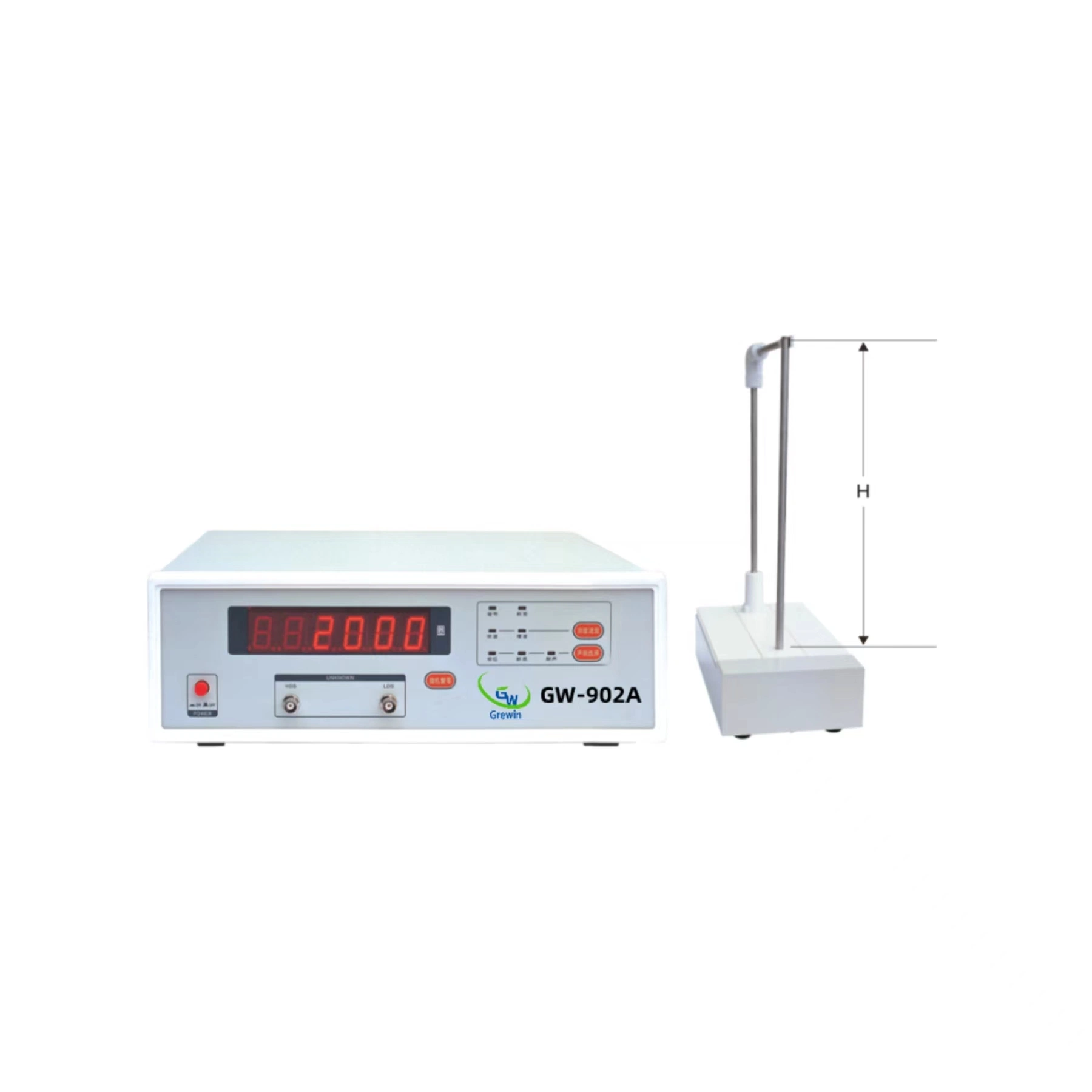
GW-902A Automatic Winding Toroidal Turns Tester for Transformer Introduction:
Coil turns tester is an equipment of good quality and low price, used to test all kinds of magnetic coil turns. Featuring strong functions, outstanding performance and easy operation, the equipment meets the needs of high-precision testing and productive spot high- speed testing.Turns Ratio Tester Technical Parameters:| Sensor height | H-250mm | H-350mm | H-450mm | H-550mm |
| Sensor diameter | Diameter ≤ 10mm Height ≤150mm |
| Testing coil inner diameter | Φ> 10mm |
| Testing coil outer diameter | Φ>120mm |
| Testing coil height | H <220mm | H <320mm | H <420mm | H < 520mm |
| Sensor specifications | 10mm |
| Testing turn number | 0-60000 turns |
| Turn number testing measurement accuracy | 0-300turns ± 0 turn, 300-500turns ± 1turn, 500-20000turns± 0.2%, 20000-60000± 0.5% |
| Testing speed | Quick: 0.35s/time, slow speed: 0.7s/time |
| Working power supply | AV220V±10% 50Hz ± 2Hz (customizable AC110V,60Hz) |
| Working environment | Environmental temperature:+5 ºC ~+35 ºC, relative humidity: below 85% |
| Dimensions | 400*132*245 mm |
| weight | About 7kg |
| Discrimination | 0.01% |
Related Products
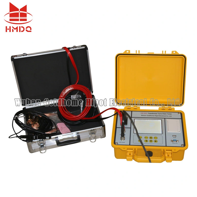
GW-900A Automatic Winding Coil Turns Ratio Tester for Transformer
Introduction:
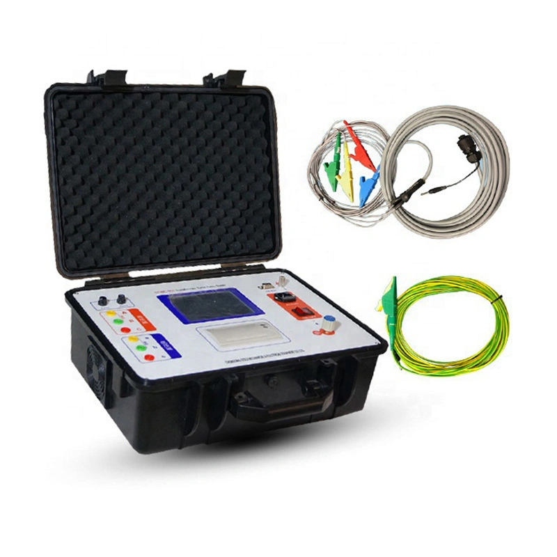
Coil turns tester is an equipment of good quality and low price, used to test all kinds of magnetic coil turns. Featuring strong functions, outstanding performance and easy operation, the equipment meets the needs of high-precision testing and productive spot high- speed testing. GW-901A Automatic EI Toroidal Transformer Coil Turns Tester for Transformer I. Overview
This instrument is used for measuring the turns of various types of coils, such as motor windings, generator windings, transformers and transformer coils, relay coils, TV HV/LV convertors, auto ignition coils.
Thanks to the precision sensor and microcomputer circuit produced with the patent technologies, this instrument features the advantages such as high precision, powerful function, low influence on the coil shapes and geometric dimensions, reliable and easy operation. Accuracy values of the measured coils can be easily read from the instrument without any adjustment and calibration to the instrument, which greatly improve the measuring efficiency.
II. Schematic Diagram III. Main Technical Index
| Specifications of Sensor | Φ2mm | Φ3mm | Φ4mm | Φ6mm | Φ10mm |
| Measurement Accuracy | 0~300 coils | ±0 coils |
| 301~500 coils | ±1 coils |
| 501~5000 coils | ±0.3% | ±0.3% | ±0.2% | ±0.2% | ±0.2% |
| 5001~20000 coils | -- | ±0.4% | ±0.2% | ±0.2% | ±0.2% |
| 20001~60000 coils | -- | -- | ±0.5% | ±0.5% | ±0.5% |
| Measuring Range | 0~5000 coils | 0~20000 | 0~60000 coils |
| Inner Diameter of Measured Coil | >2mm | >3mm | >4mm | >6mm | >10mm |
| Height of Measured Coil | ≤20mm | ≤30mm | ≤110mm |
| External Diameter of Measured Coil | ≤15mm | ≤25mm | ≤120mm |
| Working Power Supply | AC220V±10%, 50Hz±2Hz |
| Operational Environment | Environmental Temperature: +5ºC~+35ºC, Relative Humidity: 85% below |
| Overall Dimension | 370 x 220 x 110 (mm) |
| Weight | Approx. 7kg |
The measure accuracy for coils with special specification will be determined with users through consultation.
IV. Operation
4. 1. Fix measuring transducer
Insert the sensor into the corresponding slot of the right side of the instrument Connect the two measuring traverses (red & black) respectively into the wiring holes on the rear side of the instrument.
4. 2. Connect the Power Supply
Plug the power cord into the power supply socket on the rear side of the instrument and turn on the power switch. Warn up the instrument for 5min after the display is activated.
4. 3. Turn the horizontal tumbler on the measuring sensor counter-clockwise to a desired position (not exceeding 45°) and put the coil to be measured onto the test bar of the sensor. Then reset the horizontal tumbler on the sensor.
4. 4. Measurement
4. 4. 1. Connect the two terminal wires of the coil to be measured respectively with the red and black measuring traverses and make sure the electrical connections are in good condition in order to minimize the effects of contact resistance.- 4. 2. Phase Display
When the instrument is working in a continuous measuring mode after being switched on, the number of the coil turns will be displayed on the screen. The mark "-" which may or may not be shown in front of the value indicates the two different winding direction of the coil.- 4. 3. "Measuring speed" Key (there is no "fast" measuring state when GW-9108 measures the resistance)
When the "FAST" lamp is on, the instrument is working in a fast measuring mode (at a measuring speed of approx. 0.35s/time). Press the "MEASURING SPEED" key once again, the "FAST" lamp is off, and the instrument is working in a slow measuring mode (at a measuring speed of approx. 0.84s/time)- 4. 4. "Sound select" Key (GW-9108 does not have such function)
Three pilot lamps ("PHASE", "OPEN CIRCUIT" and "MUTE") on the top right of the instrument are used to indicate three sound modes The instrument can be switched among these three sound modes by pressing the "SOUND SELECTION" key. If the "PHASE" lamp is on, the alarm will sound only when the phase mark "-" is displayed on the screen or there is an electric contact error. If the "OPEN CIRCUIT" lamp is on, the alarm will sound only when the coil to be measured has an open circuit or is disconnected or there is an electric contact error. If the "MUTE" lamp is on, the alarm will sound only when there is an electric contact error
4. 5. If the measured coil has an open circuit, or is disconnected or the coil resistance is greater than 50KΩ, the instrument will display "Error".
4. 6. When there is an electric contact between the coil and the test bar of the sensor, the "ELECTRIC CONTACT" pilot lamp on the instrument will illuminate.
4. 7. If the instrument is exposed to serious electromagnetic interference and can not work normally, make sure to eliminate the interference source before performing any measurement.
V. Precautions
5. 1. Avoid any large electromagnetic interference around the instrument to avoid affecting the accuracy of the instrument.
5. 2. An open circuit inside the coil to be measured may affect the measurement accuracy.
5. 3. While putting the measured coil onto the test bar, make sure the lower end of the windings is set against the test table and the test bar is in the middle of the coil, in order not to affect the accuracy of the instrument
5. 4. Make sure there is a good contact between the coil lead wires and the wire clips.
5. 5. Prevent the test sensor from any collision and rotate it within approx. 45°avoid any damage.
5. 6. The test sensing assembly has been calibrated by using a special instrument and shall not be dismounted or modified without authorization, otherwise it will affect the measurement accuracy.
VI. Complete set of the Instrument
6. 1. GW-901 Type Coil Turns Measuring Instrument 1 set
6. 2. Power Cord 1 piece
6. 3. Measuring Line 1 pairs
6. 4. Operating Instructions 1 copy
6. 5. Certification 1 copy
VII. Storage and Warranty Period
7. 1. The product shall be stored with its original package in an indoor environment with an ambient temperature of 0~40°C and a relative humidity of not greater than 85%, and free of any hazardous substances in the air which content is enough to cause corrosion.
7. 2. The manufacturer shall provide a warranty service free of charge for any and all quality defects or malfunctions found in the product and its accessories within 18 months from the date of delivery if the user has fully observed the requirements on storage, installation and operation stipulated in the User Instructions provided by the manufacturer and the product seal is intact.
VIII. Common Faults and Elimination
No display or only one Nixie tube lights
| 1. Check if the power socket and the fuse are in normal |
| 2. Check according to each group of voltage marked on the power socket bracket, if not, repair the power supply |
| 3. Check pins (30) on main board AT89S52, if there is no high frequency impulse, replace the crystal oscillator 20MHz at main board AT89S52. |
| 4. Check if the pin between the display panel and the main board is plugged well. |
| Display instability | 1. The sensor shall be plugged properly with good contact. For discrete type, check if the two connecting wires are broken. |
| 2. Check whether the sensor works well |
| 3. Check if the steel tube of the sensor is connected well with the machine grounding wire or the enclosure |
| Breaking light constantly on | 1. Check if the output clamp is broken |
| 2. Check if the printed board of the heat sink is broken |
| 3. Check if the machine plug-ins are loose or jumped out |
| 4. If the discrete connecting wire is disconnected. |
| Shell-touching lamp constantly on | 1. Check if the clamp wire touches the enclosure or the stainless steel tube |
| 2. Check if the printed board of the heat sink is broken |
| 3. Check is the resistance 5.1Ω-0.5W of enlarge board is broken. |
| Big error | 1. If the sensor is matched with the machine |
| 2. Whether the sensor works well |
| 3. If related measuring conditions comply with other precautions |
9. 1. Within 300 turns, GW-901 instrument shall not have any error
9. 2. As shown in Fig. 9-1, Fig. 9-2 (the lead has been pass through the testing door) , it is one turn
9. 3. As shown in Fig. 9-3 (the lead is equal to not pass through the testing door), it is 0 turn, and when testing more turns, the total turns like this case shall be one turn less.
According to the above principle, the wire clamping position shall be notes.
Fig.9-1 Fig. 9-2 Fig. 9-3
X. Use ohmmeter to measure the normal sensor
10.1 Use ohmmeter to measure the integrated normal sensor (Fig. 10-1)
a. Three stainless steel tubes shall be connected with each other and connected with pins (2, 3, 4 and 5) of the sensor.
b. Te resistance of pins(1, and 10) and pins (6, 7, 8, and 9) of the sensor shall be 8--15KΩ or so.
c. The resistance of pins (12, 13, 14, and 15) and pins (16, 17, 18, and 19) shall be several hundreds of Ω or so.
10.2 Use ohmmeter to measure the discrete normal sensor (Fig. 10-2)
a. Three stainless steel tubes shall be connected with each other and be connected with pin (3) of the 3-core terminal.
b. The resistance between three pin (1) and pin (2) is about 8--15KΩ.
c. The resistance between 4-core terminal pin (1) and pin (2) of the sensor is about several hundreds of Ω.
When the above conditions are satisfied and the mutual resistances are infinite, it shows that the sensor is good, note that the potentiometer in the sensor is adjusted with special equipment and shall not be rotated when repair.
When there is fault in case of "a", check if the spring clamping sheet is contacted well.
When there is fault in case of "b" and "c", the sensor can not be repaired and only replaced
Fig. 10-1 Fig. 10-2
When the above conditions are satisfied and the mutual resistance is infinite, it shows that the sensor is good, and note that the potentiometer in the sensor is adjusted by the special equipment and shall not be rotated when repair.
★When there is fault in case of "a", check if the spring clamping sheet is contacted well.
★When there is fault in case of "b" and "c", the sensor can not be repaired and only replaced |
Company Profile
Grewin Industrial Group Co., Ltd. was founded in 1993 to provide cost-effective, high-quality manufacturing solutions for transformer industries.
Whether producing transformers, chokes,magnetics or other vital components,our winding machine are relied upon by countless manufacturers around the world.
1. Good Quality and Low Price:Our machines and equipment have long service life and high cost performance.
2. High precision and efficiency: Used to test all kinds of magnetic coil turns.Featuring strong functions, outstanding performance and easy operation, the equipment meets the needs of high-precision testing and productive spot high- speed testing.
.
3. Technical Support: Grewin can provide cost-effective winding machines to meet the needs of different customers, and provide them with products and technical support.
So whether you are a manufacturer of transformers, chokes or other winding components, Grewin's winding machine are a wise choice. With their precision, flexibility and affordability, they can help you meet your production goals while ensuring the quality of the finished product.So whether you are a manufacturer of transformers, chokes or other winding components, Grewin's winding machine are a wise choice. With their precision, flexibility and affordability, they can help you meet your production goals while ensuring the quality of the finished product.After Sales Service
PRE-SALE:
1. Strong and professional team of engineers, rich experience
2. Able to provide innovative solutions and quotes in one day.
IN SALE:
1. Delivery time: 5-10 days(standard machine), 30 days(custom)
2. Free consulting service: in-depth understanding of customer needs
3. Provide professional advice: including the choice of parts type and consumable parts of the machine.
AFTER-SALE:
1.24 hours free remote service: video guide and telephone
2. Warranty:1 year after-sales service
Our Team with Customer
Packaging & Shipping
GREWIN INDUSTRIAL GROUP CO.,LTD
Add: 2#MeiNian Plaza No.16 DongTing Road,Hexi Distrct | Tianjin | 300040 | China


 Complaint